Continue to Site

Welcome to our site!

Electro Tech is an online community (with over 170,000 members) who enjoy talking about and building electronic circuits, projects and gadgets. To participate you need to register. Registration is free. Click here to register now.

  • Welcome to our site! Electro Tech is an online community (with over 170,000 members) who enjoy talking about and building electronic circuits, projects and gadgets. To participate you need to register. Registration is free. Click here to register now.

A/D Conversion accuracy

Status
Not open for further replies.
mcs51mc said:
About the software, this is how I should do it, but since you're not me you can still do what you want :D:p:D

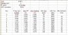
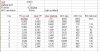
1) Use right aligned PIC data and the full 10 bits (range 0 to 1024)

2) Average successive 256 ADC readings to get 1 avgKeyValue. That is easily done by adding all ADC readings into one 24 bit variable and use only the upper 16 bits of the result. (256 readings of 1024 will result in 262144 = 040000; upper 16 bits are 0400 = 1024). I'm sure you can find math stuff on Nigel's site :)

3) Set the sampling rate of the PIC in such way that you get a avgKeyValue calculation every 0.1sec.

4) Compare succesive avgKeyValue to check if a key is pressed. If yes decode the new avgKeyValue using formula, look-up table, comparing... ... (correct choice can only be made once you know the final hardware = value for every key).

5) Wait for the "no key" code to seperate successive keys.


Some good points there that I will definitely look at. I have it working pretty well as of 11pm last night... button presses are quick and accurate so far, but can only improve with some of your suggestions above.

I have no problem entering a 4 digit code (pretty much as fast as my fingers can move), and running a "lock open" routine from there. I implemented a "4 wrong tries" lockout penalty last night, so it will lock you out if you try 4 bad combinations in a row. They are reset on a good comb entry. I've also got "manager mode" figured out with a hold down of the last digit of a valid comb -- hold for 5 seconds, you get a double beep and the LED comes on and stays on. From there, I will implement "function" buttons (ie. press "0" to change combination, press "1" to add a user, press "2" to suspend a user, press "3" to delete a user, etc.).

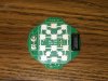
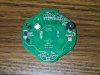
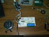
I'll take some pics today of the keypad and lock boards -- and maybe a couple of my setup. :)
 
Just a couple of images of the keypad board, and my breadboard. :)

The images of the keypad board (DCP_5411 and DCP_5412) are of this keypad -- a Lagard LGAudit 3125 Round Entry Keypad. I choose this one simply because it shows the iButton port as well. The keypad attached to my breadboard is the one I linked to earlier (3000 Round Entry). The differences are;

Mine has no iButton port, but it has two batteries under the keypad.

The LGAudit keypad (board pictured here) has the iButton port, but no batteries on the exterior at all (you must utilize the second connector on the lock board for an external source) -- however, there are two terminals (see in DCP_5411, left side of the board) that will allow you to connect an emergency 9VDC battery, in case of internal battery failure.

TV1 and TV2 are only on the board when the iButton port is present.

R11 and R12 are not on any boards that I have seen -- they are for the "*" and "#" keys, respectively.

I haven't really studied R17, but I believe it to be a resistor that can be added to the ground pads of each button, providing resistance for a "no press" situation, as I currently have a "no connection" status for the "no press" situation. The keypad has been setup for multiple uses and is used throughout their product line.

I have not attached any pics of the lock board (LaGards), simply because it is a safe lock and I don't feel comfortable in doing so, due to security concerns. If you want to discuss it with me, I have no problems in emailing select individuals images of it (you can pick a schematic from them, for sure), I just don't want to post it in an open forum. Contact me vial PM if you wish. ;)

Oh, my breadboard -- DCP_5404 -- the grey cable comes from the keypad, the black cable comes from a 9VDC regulated Wall-Wart (actually made by LaGard for their locks). It is attached to an Inchworm+ (ICD2 clone) Debugger/ICSP with the Unicorn USB upgrade (the FireFly dev board can be seen beside them) and another of my lock board projects (iButton) in the top right corner. This particular circuit, when complete, will really only be the left side of the breadboard -- the LCD is just for development/debugging (and I may even drop 16F873 for a 16F88 as I don't need the I/O on this project). The red LED simulates a connection to the lock... it will have a connector there eventually. If you look at the board in the top right of the picture, the grey cable on it goes to the lock body (and you can just see the half moon shape of the lockbolt very top, right).

(I explain everything now as someone will ask -- hey, what's that in the picture? :) )
 

Attachments

  • DCP_5411.JPG
    DCP_5411.JPG
    295.6 KB · Views: 285
  • DCP_5412.JPG
    DCP_5412.JPG
    321.5 KB · Views: 271
  • DCP_5404.JPG
    DCP_5404.JPG
    312.2 KB · Views: 392
Last edited:
Hi All;

Well, I've finally been able to get out and pick up some parts... and now I need a little help! :)

I'm completely lost with the wiring of the op-amp. Well, I thought I understood it, but even the most rudimentary circuits don't want to work for me.

I didn't know what a voltage follower was, so I Googled it -- no problem, looks pretty straight forward (I told you I'm not a hardware guy!).

Today, I bought an LM358, single supply, low-voltage, dual op-amp and have been trying to wire it up since I got home. Right now I'm down to Vcc and GND wired to the LM358. That configuration produces 3.80VDC at both 1out and 2out (pins 1 and 7 respectively). If I add 4.98VDC to 2in+ (pin 5) and then return 2out (pin 7) to 2in- (6), should this not be a voltage follower and produce the input voltage at 2out (4.98VDC)? I still get 3.80VDC. It doesn't seem to matter how I wire it, I still get 3.80VDC. I've tried with an 8K2 wired to 2in+, I've tried a 1K between 2out and 2in- with another 1K between 2in- and GND and get 3.80VDC (I believe this is an non-inverted amplifier). (I'll have to draw up some schematics to make it easier to understand -- but these are all various methods of wiring an op-amp that I have found on the web).

(You're going to ask me why 1K above? The formula I found for gain was gain = RA/RB + 1, so 1K/1K = 1 + 1 = 2 was what I was thinking. Following that theory, I could have used any two values, as long as they were the same to divide against themselves.)

Anyway, I figure I'd get it to work as a voltage follower and then worry about gain... I am lost when it comes to "set a gain of 2". From what I understand, a voltage follower has unity gain (a gain of 1)... so how do I set it to 2? If I do set it to 2, wouldn't that be a non-inverted amplifier and not a voltage follower?

I have not been able to find a definition for "lock resistor" either (term used by mcs51mc a few pages back).

Thanks again!
 
Here are a few of the various ways I've tried to wire up the LM358.
 

Attachments

  • op-amp_wiring_attempts.jpg
    op-amp_wiring_attempts.jpg
    160 KB · Views: 302
Kyle-s4h said:
Today, I bought an LM358, single supply, low-voltage, dual op-amp and have been trying to wire it up since I got home. Right now I'm down to Vcc and GND wired to the LM358. That configuration produces 3.80VDC at both 1out and 2out (pins 1 and 7 respectively). If I add 4.98VDC to 2in+ (pin 5) and then return 2out (pin 7) to 2in- (6), should this not be a voltage follower and produce the input voltage at 2out (4.98VDC)? I still get 3.80VDC. It doesn't seem to matter how I wire it, I still get 3.80VDC.
Although you correctly chose a single supply op amp, it must also be capable of swinging to the positive rail. The LM358 can swing to ground, but not to Vdd. Google for "Rail-to-rail operational amplifiers".

Kyle-s4h said:
Anyway, I figure I'd get it to work as a voltage follower and then worry about gain... I am lost when it comes to "set a gain of 2". From what I understand, a voltage follower has unity gain (a gain of 1)... so how do I set it to 2? If I do set it to 2, wouldn't that be a non-inverted amplifier and not a voltage follower?
A voltage follower has unity gain: outout voltage = input voltage (U1:A in your schematic). It just changes high impedance inputs to low impedance.

mcs51mc suggested a gain of 2 because, according to his calculations, you get better values. A gain of 2 is achieved with the 'non-inverting' configuration (U1:B).

Kyle-s4h said:
(You're going to ask me why 1K above? The formula I found for gain was gain = RA/RB + 1, so 1K/1K = 1 + 1 = 2 was what I was thinking. Following that theory, I could have used any two values, as long as they were the same to divide against themselves.)
Yes, the resistors must be equal. The value shouldn't be very low or very high and the choice depends on other parameters too. In the 10 k range for an LM358, in the 100 k range for a C-MOS op amp.
 
Last edited:
Thanks for the explanation, eng1. It all makes sense when it is explained, but can be very frustrating when it doesn't work, and there seems to be no logical explanation as to why.

Well, yeah, if you buy the right chip -- duh! LOL!

Not knowing anything about op-amps, I simply searched for what was recommended -- an op-amp that is low-voltage and single supply. I didn't see anything about swinging to the positive rail -- oh well, today's another day! The unfortunate part was, I made the trip to Creatron today because Lawrence is quite knowledgable in the hardware end of things and usually helps me out with questions and explains what things are, and what they do. Of course, I have to pick a day when he is not there and I get a 15 y/o kid who didn't know what an H-Bridge was when I asked for one... so there was no way he could answer questions about the proper op-amp choice. I simply scoured the IC wall for "single supply, low-voltage" -- and saw the LM358.

I have been wanting to try the op-amp since you all have suggested it as I would really like to get the figures that msc51mc has provided. Reason being I would like to design a tool to check the keypad itself (one of the common problems in service is a bad keypad). Having a greater bit range between keys would allow me to float quite a bit on either side for testing the pad.

As for the resistor value -- funny, I had 10K's to start with (in my calculations), but took them out thinking they were too high (like my 22K resistor at the beginning of this post!).

I will Google "Rail-to-rail operational amplifiers" and do some reading -- thanks! The problem I find though is there are simply so many parts out there -- I read and read and make a decision, then go to the electronics store (closest one to me is a 30 minute drive) and find "we don't carry that part" -- but they have 400 others of that "type" of part. Then, they (store employees) can't help you because they don't know anything about the product either. Kinda like this op-amp -- It's a 40 minute drive to get another.

Could you imaging going to Home Depot for some paint and when you ask them a question about enamel paint, they say "what's the part number?" Or how about buying a new drill press and the salesman repeatedly says "I don't know"? If I ran my business like some of these electronic stores, I'd have been out of business 20 years ago (like the week after I started).

Thanks again, eng1 -- let's hope I can find the actual part after I Google it! ;)
 
This is proving to be quite challenging!

I went to a local guy (which I really knew better -- he's more of a "surplus" (bought it 'cause it was cheap) kinda place, although he claims to be an electronics store) -- he had a wall full of NTE parts, but no way for me to identify what they were. I spent about 20 minutes browsing through a catalog, which proved to be a big waste of time. No wonder all the bags the parts are in look like they've been hanging there since 1970. I even gave him a couple of numbers I found when reading on "rail to rail op amps" -- but he couldn't cross ref them.

So, back home I am. Now, I'm looking on Sayal website. They don't give you much information either, and when you do find a part you *might* be interested in, you can't find a datasheet on it (are they using full part numers?). I find 324-2 (QUAD OP AMP LOW POWER) - but a Google search doesn't give me any info on that part number (5 results, most of them to "electronics parts search engines"). Another says 062CP-1 (OP-AMP DUAL BIFET LOW POWER), but I can't find info on that either. Sure as sh*t if I drive there and ask questions about them I'm going to get the blank stare and "I don't know -- what's the part number?".

Can anyone take a quick look at the sayal page and see if any of these are what I need? PLEASE? **broken link removed**

I'm going to call Lawrence at Creatron and see if he's there (otherwise that would be a wasted trip as well, as my experience yesterday proved).

Thanks again for your help!
 
Lawrence is at the store and has a few rail to rail op amps to choose from. I told him I bought the LM358 there yesterday and he immediately said "nope, wrong one -- not rail to rail" -- (man, it's nice to talk to someone who knows their stuff) -- I am on my way to chat with him -- just wish he was there yesterday! :)
 
I have to put in a plug here for Lawrence at Creatron -- it is such a treat to be able to talk to someone who knows their stuff. (Creatron -- 255 College St., Toronto, ON M5T 1R5 416-977-9258)

Not only was I able to find the correct op-amp, I received a 10 minute course on how they work and why, what the difference between "rail to rail" and standard is and why I need "rail to rail". I had no idea what you guys were talking about as far as the "swing", but now understand that as well.

Oh, yeah, I ended up with an LMC6462, Micropower, 3/5V, single supply, rail-to-rail, dual CMOS.

At the same time, I took advantage of my trip and asked about the 3V power supply I needed, as well as a low quiescent fixed 5VDC regulator (as pointed out earlier for battery operation). I ended up with an LD1086 3.3V regulator to run a small stepper motor project and an LT1521CS fixed 5VDC regulator. The LT1521CS is SMD though -- it will be great for the finished product, but won't work for the breadboard (unless I feel like making an adapter) -- besides, the breadboard is on a Wall-Wart now, so no biggie. :)

Now, I have to go dig up a couple of datasheets and get back to testing!
 
Last edited:
Well, just a small update for y'all...

The op-amp is working out awesome! Thanks eng1 for mentioning it... and to mcs51mc for the awesome calculations! I didn't realize we had Reputation here, so I've gone back and spread some around! ;)

Here are some real world numbers that I am getting now (bang on, mcs51mc!) -- everything matches up, except for the ADC, simply because I haven't gone to 10bit ADC yet... I'm still reporting what I'm seeing with 8bit ADC -- but I'm happy with what I see! :)

Thanks again -- I'll keep you updated. :D
 

Attachments

  • tmp_opamp_adc_chart_01.jpg
    tmp_opamp_adc_chart_01.jpg
    59.6 KB · Views: 250
Now we're seeing some good numbers!

Here's some more real world numbers with 10bit ADC that has been right justified. :)
 

Attachments

  • tmp_opamp_adc_chart_02.jpg
    tmp_opamp_adc_chart_02.jpg
    62.2 KB · Views: 253
It's looking good. It's going good. We're getting great pictures here from Toronto Canada... ...

Keep up the good work... ...
 
I realize Kyle-s4h's profile is banned, but none-the-less would be interested in connecting with him.
I am interested if his lagard project got anywhere interesting.
 
I realize Kyle-s4h's profile is banned, but none-the-less would be interested in connecting with him.
I am interested if his lagard project got anywhere interesting.

No, it didn't.
 
Status
Not open for further replies.

Latest threads

Back
Top