kinarfi
Well-Known Member
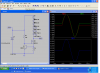
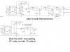
When I took electronics in 1970, the instructor showed a "CRD" that regulated the current and could be adjusted and it held a very stable current as voltage varied. I've used them several times, but now I need one that can handle 800 to 1000 ma.
Any one have any ideas,
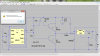
Another project is a 12-14 volt to 18 volt DC converter to power a lap top in a vehicle.
Any suggestions?
Kinarfi
Any one have any ideas,
Another project is a 12-14 volt to 18 volt DC converter to power a lap top in a vehicle.
Any suggestions?
Kinarfi
Attachments
Last edited: