Continue to Site

Welcome to our site!

Electro Tech is an online community (with over 170,000 members) who enjoy talking about and building electronic circuits, projects and gadgets. To participate you need to register. Registration is free. Click here to register now.

  • Welcome to our site! Electro Tech is an online community (with over 170,000 members) who enjoy talking about and building electronic circuits, projects and gadgets. To participate you need to register. Registration is free. Click here to register now.

6 LED 2v into 5v DC

Status
Not open for further replies.
Sure, it will work fine.

Ron
 
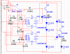
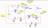
I got a idea, I though that maybe I should use 2 switch when both of them are open the red light are on, then when one of them is close the capacitor or something give some sec of current to the red led then when it's empty the red led turn off and green led turn on because another capacitor or something is full. For the other switch I would like when close to simply turn off the red led after some sec and keep both red and green leds off.

Of course both switch will never be closed at the same time

Do you know how I could make that?
 
Instead of using a battery I'm trying to use the usb port
Is the keyboard USB or PS3? You can get more power from the PS3 keyboard port than from a USB port.
my red light is for the first seconds
If your red LEDs can be on when ever the gear is not down and locked than you can just use the NC contact on the micro switch for the red LEDs and not need to do anything eles.
 
I would like to turn the red leds off when i press a switch. Do you know if is possible to press a switch and lets discharge the capacitor so the led will turn off after few sec?
 
Basicly a breadboard is useful for testing because if I make a error it will not blow up but if I simply want to build my own board is that complicated to make a safety system? I mean I have a power adapter 5vdc that plug into a electric outlet so I think I can add like a resistor with a led on the - wire so if a shortcircuit happen the light will turn on and avoid a big explosion ?
 
Basicly a breadboard is useful for testing because if I make a error it will not blow up but if I simply want to build my own board is that complicated to make a safety system? I mean I have a power adapter 5vdc that plug into a electric outlet so I think I can add like a resistor with a led on the - wire so if a shortcircuit happen the light will turn on and avoid a big explosion ?

No that will not work. A simple fuse will. Anytime you have current flow the LED would light and drop voltage.

Ron
 
So to protect my circuit to blow my usb port in case of a shprt circuit or a over load a fuse is a good idea? If it is which will be appropriated for my 100mA 5vdc circuit from usb port? Also may I cut the usb wire that connect to the adapter and plug the fuse on it ?
 
Last edited:
I would place a 250 mA (1/4 amp) fuse inline with the USB supplied 5 volts before it feeds your circuit(s).

Ron
 
Sorry if I look stupid but the 250mA fuse will cut the current if the mA goes at 250mA? If that's correct the port will be overloaded by 150mA no?
 
OK, depending on what you can get, the best choice would be a Cooper Bussmann GDA-100MA fuse. Cooper Bussmann being the manufacturer and GDA-100MA being the part number. I don't know your location or what you have for parts houses. Fuses like this aren't always a common stock item with many distributors.

Ron
 
Ok thanks,

If you can check my circuit and give me any tip of advise so I can improve it. I want to charge a capacitor for the red led but I dont want to turn on the led while charging. I only wanted to be able to discharge the capacitor through the led using the up switch.
 

Attachments

  • circuit2.png
    circuit2.png
    17.6 KB · Views: 182
That won't work. First I see C1 and C2 as .03 Farad? That would be a 30,000 uF capacitor. The RC time constant would be about 4.5 seconds to charge the cap to 63% of V supply or about .63 * 5 = 3.15 Volts. So what happens after one RC time constant? The capacitor continues to charge. Matter of fact after five RC time constants (about 22.5 Seconds) your capacitor will charge to V supply or in this case 5 volts. That same 5 volts will be across the LED. This won't matter because after just one RC time constant your LED is dead. It will be out of its misery. :)

See the attached circuit. It is about what you have.

As to your RC time you will be hard pressed to find a 30,000 uF capacitor. Well in a small package anyway.

Read this link to better understand RC time constants and what happens as a cap charges. Note the curves as to voltage and current.

You want to maintain a current limiting resistance in series with your LED. The downside of all of this is that the LED will start with a dim glow and eventually reach full intensity.

Ron
 

Attachments

  • RC Time Cap.gif
    RC Time Cap.gif
    5.9 KB · Views: 153
Just to bring back the safety fuse I found this: BK/GDA-100MA Cooper Bussmann Fuses are you sure that will help protect my usb port from being overloaded ?

Also check what I found Gear up/down indicator That's exactly what I want but I would like to have 3 red led instead of only 1. I hope you can check the circuit and help me understand it because I have no idea how to read it and where to begin ;)
 

Attachments

  • circuit3.png
    circuit3.png
    40.4 KB · Views: 162
Last edited:
This is powered from 12VDC and should work. You can wire up the three red LEDs just like the green ones.
 
Status
Not open for further replies.

Latest threads

New Articles From Microcontroller Tips

Back
Top