Continue to Site

Welcome to our site!

Electro Tech is an online community (with over 170,000 members) who enjoy talking about and building electronic circuits, projects and gadgets. To participate you need to register. Registration is free. Click here to register now.

  • Welcome to our site! Electro Tech is an online community (with over 170,000 members) who enjoy talking about and building electronic circuits, projects and gadgets. To participate you need to register. Registration is free. Click here to register now.

6 LED 2v into 5v DC

Status
Not open for further replies.

exomic

Member
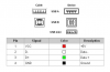
Hi, I'm building my own flight simulator for my computer and I need more information on how to plug 6 LED 2v in a 5v DC (from my USB to gameport adapter).

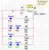
What I want to do is to delay each light from turning on when I switch to circuit on. There will be 3 Green light (representing the safe and lock landing gear light) and 3 Red light (reprensenting the unsafe landing gear light). To make that more realistic I want to make a custom timer before the green light turn on.

When I turn the circuit on I want to see the 3 red light turning on. After 3-4-5 sec one of them will turn off and a green light will turn on right after the red one turn off. The green light cannot be on if the red one is on because the red one mean the gear is not locked so is impossible to see red and green at the same time.

I saw some theory on the Timer555 be as I new member in the electronic world I'm unsure how I maybe proceed.

Thanks

PS: My led are 2v but I saw another kind for light that is for 120v with or without resistor build in so please dont laught to me if I'm appear to be a noob but I'm wondering if I can use a 120v light into a 5v current?
 
Last edited:
I won't say what you want to do is impossible but what you are looking to do is fairly complex and would require considerably more circuitry than a lowly little 555 timer chip. Much, much more and even more if you want in any way to actually interface with the game. Beyond using a pile of discreet components (chips, resistors, capacitors and whatever) you could consider the use of micro-controller which would necessitate you learning micro-controllers and how to program them. Again, not quite that simple. I am not trying to discourage you but let you know that all this is not a simple task or circuit. Blinking a few LEDs with a 555 is one thing and you have another.

Before you plan to power anything off the USB port(s) I suggest you learn their power capabilities. The 5 volt power from a USB port is limited and one small boo boo can render the port dead. I would avoid using 120 VAC for anything for the time being.

Ron
 
I know that some made a far more complex circuit to link the light with the game but I'm new in electronic so I simply wanted to delay the light from powering on after I turned on a switch, is that possible?

I'm using a USB to gameport adapter (I was based on this tutorial **broken link removed** ) so when is pluged, my pc recognize it as a joystick, so instead of plugin in a analog joystick, I'm using the pin for button and axis. I saw that there was some 5v pin so I was wondering to use it for my LEDs. You are saying that is a dangerous thing? Should I use a usb hub for my testing?

Thanks guys for your help
 
Last edited:
Hi Again

Actually, this is what I said:

Before you plan to power anything off the USB port(s) I suggest you learn their power capabilities. The 5 volt power from a USB port is limited and one small boo boo can render the port dead.

Attached is a pin-out drawing of a USB 2.0 port. As you can see there really isn't much to it. Pin 1 is 5 volts, pins 2 & 3 are data and pin 4 is ground. So yes, there is +5 volts and ground available on the port. However, much unlike the +5 volts used within the rest of the PC the USB ports offer limited current. This is what the USB specifications have to say about it:

The USB 1.x and 2.0 specifications provide a 5 V supply on a single wire from which connected USB devices may draw power. The specification provides for no more than 5.25 V and no less than 4.75 V (5 V±5%) between the positive and negative bus power lines. For USB 2.0 the voltage supplied by low-powered hub ports is 4.4 V to 5.25 V.[32]

A unit load is defined as 100 mA in USB 2.0, and was raised to 150 mA in USB 3.0. A maximum of 5 unit loads (500 mA) can be drawn from a port in USB 2.0, which was raised to 6 (900 mA) in USB 3.0. There are two types of devices: low-power and high-power. Low-power devices draw at most 1 unit load, with minimum operating voltage of 4.4 V in USB 2.0, and 4 V in USB 3.0. High-power devices draw the maximum number of unit loads supported by the standard. All devices default as low-power but the device's software may request high-power as long as the power is available on the providing bus.

The above quote was taken from here.

Pertaining to a USB 2.0 port what all of that comes down to is that unless request high current from a port the available current defaults to 100 mA. This is also subject to vary with different motherboards. Some motherboards offer over current protection while some don't. Much of it becomes a crap shoot.

There are countless articles out there on powering things from the USB ports of a computer. The problem is and what many fail to mention is if an enthusiast manages to short the 5 volts there will be a tiny spark and a good, very good chance the port will be rendered useless. Nothing wrong with using a port for power, however, you have to understand the USB port and know its limitations. That was my point. :)

As to the use of the 555 timer chip. The 555 has been around a long time. Extremely versatile little 8 pin chip for a host of timing (and other) applications. The 555 will easily act as a "Delay On" timer where when power (or a trigger) is applied the output can be delayed for a given period of time. That output can drive a small relay or a LED. Several examples of using the 555 configured for delay on can be found here.

So lighting a few LEDs with a delay following a trigger is no problem. However, when we begin adding other timed functions then things can become more complex.

What I suggest is that you find yourself a small prototyping bread board and begin to experiment with a few 555 chips and a handful of components. Anyone here will likely be happy to help you along providing small starter circuits or linking to circuits.

Ron
 

Attachments

  • USB 2 Pinout.png
    USB 2 Pinout.png
    35.6 KB · Views: 339
Thanks, but if I'm using the converter usb to gameport is that more safe? My 6 led are 2v so it should work ?

What I should not do to avoid blowing my usb port. I mean if I wire the 5v to another 5v what should happen?

I would like to make some test using a software what do you recomand?
 
The trick with USB ports is not to overload a port.

Now here is the thing with LEDs. It becomes a matter of specifications. Yes, your LEDs are 2 volts and that is the forward voltage drop across the LED. Each LED also has a forward current that you don't mention. Believe me it is there. Understand that the lowly little LED is actually a current device. So if I have a 2 volt LED and I apply 2 volts to it the LED will draw its rated current and everything will be fine and wonderful. However, if I apply more than 2 volts to my LED it will draw more current in excess of its rated current and it will become very unhappy. Depending on the over voltage it can vary from a very short and bright life to a real quick blink ( a bright blink) and that is it.

Attached is an image of two circuits. Each is powered by 5 volts (V supply) with the supply limited to 100 mA just like a default USB current limit. One circuit will overload the USB port and one will not. Each circuit has 6 LEDs with their specifications provided. Each circuit had resistors in it to limit the current through the LEDs. You tell me? Which circuit will overload the port and why?

Ron
 

Attachments

  • LEDs 1.gif
    LEDs 1.gif
    21.2 KB · Views: 274
Ok so the usb port can supply upto 100mA but as I said I'm using a USB to gameport converter so maybe the converter already use some mA? I have 3 pin of 5V DC+ so I think all of them need to be below 100mA. Am I right?

I'm currently doing my circuit and I will send it here so you can check if there is anything that make no sense.


Thanks for your precious time!
 
Last edited:
You post your circuit and we will see what you have. Also yes, the converter uses some current and my time is not that precious. I come here for relaxation, especially on my weekends. :)

Ron
 
There is my idea, if I put a timer or something to delay the light from turing on before each resistor will it take some mA? Also I dont want to have green and red led on at the same time, I want to turn the NoseR led off after like 2 sec and when off, turn on the NoseG and keep it on as long as the switch is close. For the LeftR and RightR I want to turn them off after 4 sec and then turn the LeftG and RightG on.

I dont know how or if my idea is possible to do using something simple and not too complicated so I dont need to go at university to complete it ;)

PS: Any idea how to know if I ever go over load on my usb port because I dont have any idea if the converter or simply the other 8 axis and button take allot or not.
 

Attachments

  • circuit.png
    circuit.png
    19.2 KB · Views: 219
I think the I: 82.3mA is generated by the program by considering a red led vf = 1.83V @ 20mA and the green led vf = 2.13V @ 20mA

Just to make sure you understand what will be activating the switch look at this: **broken link removed** That's what I'm doing and the switch for the led is the microswitch. Instead of using a battery I'm trying to use the usb port and my red light is for the first seconds when you lower the landing gear and the gear is not locked and then the green turn on and the pilot know that the gear is successfully locked.
 
Last edited:
Your circuit as drawn mimics mine as to Vfwd = 2 volts and I fwd = 20 mA. If that is true you have 4 legs and each is 20 mA so you have 4 * 20 mA = 80 mA.

To calculate the resistor:

Vsupply - V led / I led

So for a single LED it becomes 5 - 2 = 3 / .020 = 150 Ohms If you have 2 of the same LEDs in series then you add them so you would have 5 - 4 = 1 / .020 = 50 Ohms.

As to the timing, that is another story. I suggest you read a little about 555 timing applications. That would be a good start.

Ron
 
This Is my Leds:

Red: **broken link removed**

Green: **broken link removed**

I saw on some website that the Voltage change depending on the color of the led but the store simply wrote 2v for both red and green color. What do you think of that?
 
Last edited:
I wish they would have listed the forward current. Yes, as you mention, depending on color they can vary as to forward voltage and current. I have used some like the linked ones and they were 5 volt with an interval current limiting resistor. Anyway we can likely work with 20 mA. You will get a 150 Ohm and a 51 Ohm as 50 is non standard for off the shelf resistors.

Ron
 
After some research on internet I found something to delay leds using resistors and capacitors. **broken link removed**

Instead of using a complex 555timer I think that may be easier.

My question is how do I avoid using over 100mA if I dont even know how much the adapter, capacitor, resistor and other axis and button uses on the same port?
 
That would work. Get a few LEDs and try it. You may find how the LED turns on to be interesting.

I have no clue what the current draw of the dongle is. The only accurate way to know would be to measure it. I doubt it is much at all as devices like this are designed to be low current devices. For all I know, the device may be one that does request high current from the port? I don't know.

Ron
 
Last edited:
Just a thought on the current draw of the LEDs. Many are typically rated at 20 mA, but that doesn't mean you have to run them at 20 mA. For many applications, the LEDs will be bright enough at 10 or even 5 mA. You can always use higher-brightness LEDs (say 1000 mcd or higher) and drive them at lower currents. This is a good way to conserve battery (or in your case, USB) power.
 
After some testing with resistors and capacitor I dont get what I want or maybe I dont know how to do it. The capacitor do is job, it charges and discharges but what i'm looking for is simply to delays the led from turning On when I press the button and when I release take some time before turning off.

I tested the 555 timer but I only got a power cycle in loop (led turning on and off) instead of just 1 cycle :(

Hope someone can help me with that or I will need to stay with basic circuit and forgot the delay for the light so it will be less realistic but will do the job.
 
Last edited:
Post your 555 circuit. You want a delay on make 555 circuit.

I told you that you would get an interesting effect using the cap and resistors. When you release the button the cap needs to discharge so the LED remains illuminated until the cap discharges below the LED threshold voltage. They mention that in the link.

Doing what you want to do is not quite as easy as it looks on the surface. The ideal solution for something like this would be to use a PIC Chip (u-Controller) which would necessitate learning how to program them. Using discreet components for timing applications like this can get a little complex.

Also, kpatz makes a good point as to the current. 10 mA would likely do fine reducing the overall current.

Ron
 
May I use a 120vac switch for my 5vdc circuit?

Huh? You lost me with that one? What do you mean? Unless you mean use a switch rated for 120 V to switch 5 V instead? Then the answer would be yes. You are talking about just a switch right but no actual 120 vac involved correct?

Ron
 
Status
Not open for further replies.

New Articles From Microcontroller Tips

Back
Top