hi everyone
as a way of intro: I am new to this site and a relatively new electronics hobbyist.
A quick summary of my circuit:
I built a simple circuit with a 74HC595 w/ 8 output LEDs. I am looking to hook up the QH' back to the shift register's input pin. But, have not been able to get it to work. The circuit works just fine just as a basic shift register w/o the "ring" capability.
This below set up works as a basic shift register
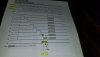
The circuit uses :
I took the QH' pin (p9) and connected that back to p14/Data and that does not seem to work as as ring/loop back. In my limited datasheet reading/knowledge, it appears that I might need to insert a timing delay before I loop back. What I mean by that is, in looking at the timing diagram, The QH' goes HIGH at the 1/2 time mark of QG/high-pulse window and remains high through QH's 1/2 high-pulse. The QH's high pulse remains high after QH' falls low. My newbie brain tells me that I might need to wait till after QH falls to low before I can connect the QH' back to the input. .
Question:
Can someone please comment / clarify and provide any pointers to me or example of how one should get this to work please.
thanks
as a way of intro: I am new to this site and a relatively new electronics hobbyist.
A quick summary of my circuit:
I built a simple circuit with a 74HC595 w/ 8 output LEDs. I am looking to hook up the QH' back to the shift register's input pin. But, have not been able to get it to work. The circuit works just fine just as a basic shift register w/o the "ring" capability.
This below set up works as a basic shift register
The circuit uses :
- 555 astable as a clock pulse into the 74HC595/SRCLK/main Clock/p11,
- a separate 555/monostable/debounced switch as input into the 74HC595/SER/Data/p14,
- and an NPN as an inverter for the 74HC595/RCLK/Latch/p12.
I took the QH' pin (p9) and connected that back to p14/Data and that does not seem to work as as ring/loop back. In my limited datasheet reading/knowledge, it appears that I might need to insert a timing delay before I loop back. What I mean by that is, in looking at the timing diagram, The QH' goes HIGH at the 1/2 time mark of QG/high-pulse window and remains high through QH's 1/2 high-pulse. The QH's high pulse remains high after QH' falls low. My newbie brain tells me that I might need to wait till after QH falls to low before I can connect the QH' back to the input. .
Question:
Can someone please comment / clarify and provide any pointers to me or example of how one should get this to work please.
thanks