Roff
Well-Known Member
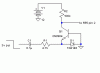
This schematic is in response to Flextronics's post under General Electronics chat:
https://www.electro-tech-online.com/threads/okay-got-a-bit-of-a-problem.2125/
This assumes that your 0 to -2v source can drive the load, which is basically 4.7k.
Ron
https://www.electro-tech-online.com/threads/okay-got-a-bit-of-a-problem.2125/
This assumes that your 0 to -2v source can drive the load, which is basically 4.7k.
Ron
")
