Continue to Site

Welcome to our site!

Electro Tech is an online community (with over 170,000 members) who enjoy talking about and building electronic circuits, projects and gadgets. To participate you need to register. Registration is free. Click here to register now.

  • Welcome to our site! Electro Tech is an online community (with over 170,000 members) who enjoy talking about and building electronic circuits, projects and gadgets. To participate you need to register. Registration is free. Click here to register now.

555 Timer for a relay

Status
Not open for further replies.
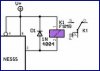
In the circuit that is attached to the first post of this thread there is a strange connection of the transistor that drives the relay.

If you use a transistor connected to +Vcc, it must be a PNP with emitter connected to +Vcc and collector towards the relay coil (in the schematic, it's an NPN connected in reverse).

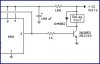
If you want to use an NPN, use it with emitter towards GND and collector toward coil as in the second schematic posted in the thread.

Indeed, the relay contacts for the flasher (first schematic) are completely wrong.
 
GOT THE LED TO FLASH! haha finally, so how do i make the output signal actiuvate the relay? somebody please make a schematic for this lol i need a seperate ojne cause the diagram i used is not the one boncuk posted haha and what transistor can i use? radioshack only please
 
Last edited:
The standard 555 (not the CMOS version!) may drive a 200mA relay so you may drive a relay directly without transistor. If the relay is bigger, try the circuit with transistor.
Below you find an example of direct drive and of transistor drive (just look at pin 3). In both cases, the diode in parallel to the relay coil is mandatory.
 

Attachments

  • 555-1.JPG
    555-1.JPG
    13.7 KB · Views: 192
  • 555-2.JPG
    555-2.JPG
    18.6 KB · Views: 211
why is the diode necessary? im just curious. i got it to work before your post lol but thank you.

when the relay is switched off, the relay coil produces back emf of high voltage and in reverse direction to normal potentials. this would damage the transistor driving the rely.
the diode provides a current path for this back emf so that the drive Transistor is safe. Hope you get it. this would be taught in fundamentals of inductance and Dc and ac circuits involving inductors.
 
Status
Not open for further replies.

Latest threads

New Articles From Microcontroller Tips

Back
Top