Continue to Site

Welcome to our site!

Electro Tech is an online community (with over 170,000 members) who enjoy talking about and building electronic circuits, projects and gadgets. To participate you need to register. Registration is free. Click here to register now.

  • Welcome to our site! Electro Tech is an online community (with over 170,000 members) who enjoy talking about and building electronic circuits, projects and gadgets. To participate you need to register. Registration is free. Click here to register now.

555 Timer for a relay

Status
Not open for further replies.
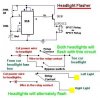
Ok so i want to wire something that will activate a relay on and off repeatedly [on .5 sec, off .5 sec] repeat. i got this circuit and tried wiring it and it did not work, can somebody check this for me? and if its not right can somebody redraw it for me correctly, and i am not sure where power is applied but i believe it goes to the link between the 200k resistor, and pin 8, etc. One other question, how do u identify the orientation of the chip? and if anyone has a better or different circuit using only parts available at radioshack then please post asap. this is for a headlight wig-wag system, so i plan on using a spdt relay and a switch. thanks!
 

Attachments

  • Headlight_Flasher.jpg
    Headlight_Flasher.jpg
    29.3 KB · Views: 2,041
Last edited:
Hi,

there is no circuit posted.

You can identify an IC orientation from top. There should be a notch at the left hand side.

For the pin count refer to the attachment.

Boncuk
 

Attachments

  • DIP-08.gif
    DIP-08.gif
    7.3 KB · Views: 503
Just in case you've made a mistake:

This circuit switches every 1.066secs.

Boncuk
 

Attachments

  • Tmr-off.gif
    Tmr-off.gif
    11.2 KB · Views: 710
  • Tmr-on.gif
    Tmr-on.gif
    11.2 KB · Views: 803
and what is a "c 10n? is that a ceramic cap?

i have an assortment of ceramic caps, the 222 transistor, the 555 ic, tons of resistors
 
Last edited:
If that design did nothing the malfunction might be found searching right between the hands and one store up. :)

The 10n cap might be anyone you find in your junkbox. If you don't have one just leave pin5 unconnected.

As you can see from my post the relay (animated) really works (open and closed) - without clicking.

Recheck your wiring. The 1µ electrolytic cap should be connected to ground with the negative terminal.

If your chip hasn't gone across the river Jordan already it should work like a charm.

Boncuk

P.S. Next time you post here I want to read "Hurray!" If you used the pot take the wiper to the center position first. The circuit does nothing if the wiper is brought into a position to have pin7 connected to +UB (thus omitting the resistor).
 
Last edited:
The first time I built a 555 LED flasher, I pulled my hair out for hours. Theres even a topic on here I posted. If any one thing isn't exactly right, it won't work and may burn out the 555.

Do you have a protoboard? Or are you soldering this?

If you have a protoboard, start with making the 555 just blink an LED, then add your transistor and relay. That way you know the 555 is working, and if it it dosn't work with the relay, you have a problem with the transistor or the relay and not the 555.

I don't see a freewheel diode in your drawing. I would add one to keep the relay from damaging the transistor.

Also, powering the 555 backwards kills them from my experiance.
 
Alright so i wired this circuit up and it didn't work. I used a 5.6K Ohm and a 4.7K Ohm for r1 and r2. i tried both my 555's on this an d it didn't work


**broken link removed**
 
This circuit actually does something, but may be you don't see what it's doing. The output frequency is about 10Hz at a duty cycle of almost 80%.

The description of VDD (+5 to 15V) seems a bit vague to me, since the LEDs won't light at a supply voltage of +5V having current limiting resistors at relatively high values, resulting in an LED-current of approximately 3mA.

What is the problem using parts as I recommended for a clock cycle of 1Hz and a duty cycle close to 50%?

For visible (and audible) results please refer to the suggested circuit.

Boncuk
 
If that design did nothing the malfunction might be found searching right between the hands and one store up. :)

The 10n cap might be anyone you find in your junkbox. If you don't have one just leave pin5 unconnected.

As you can see from my post the relay (animated) really works (open and closed) - without clicking.

Recheck your wiring. The 1µ electrolytic cap should be connected to ground with the negative terminal.

If your chip hasn't gone across the river Jordan already it should work like a charm.

Boncuk

P.S. Next time you post here I want to read "Hurray!" If you used the pot take the wiper to the center position first. The circuit does nothing if the wiper is brought into a position to have pin7 connected to +UB (thus omitting the resistor).


Well, i think you may be right about the 555 timer dying haha. but beside that are you saying that the relay will NOT click when activated? because thats what i was listening for as opposed to making a whole rig to test it to axtual lights. and i am going to try to mock this up again with a new 555 and see what happens haha. ill let you know, thanks for bearing with my newbie-ness haha.
 
... but beside that are you saying that the relay will NOT click when activated?

Of course a simulated relay doesn't click since it has no audio output. :D

The switch position can clearly be seen looking at the two screenshots.

Boncuk
 
How much current does the relay coil need?

If the coil needs 200mA or less then the 555 can drive the relay directly, no transistor required.
 
He meant to connect pin4 to +VDD as pin8 is. Pin4 unconnected or pulled to ground resets the timer continously.
 
So ive tried 3 diff circuits including urs boncuk, cannot get any of them to work. id baffled right now. i have tried multiple different 555s and no results, i tried mocking it up on solderless breadboard and still couldnt get it right
 
This is the best thing you can do. The circuit must work if wired properly.

Rip up the whole thing and completely wire it new.

There is certainly a faulty connection somewhere and you won't stumble over it trying to correct.

Don't fry the timer circuit ICs unneccessarily.

Boncuk
 
Status
Not open for further replies.

Latest threads

New Articles From Microcontroller Tips

Back
Top