Hi,
Since I have a number of large LCD's which require negative voltage for the glass (-8 to -25V @ 8mA max) rather than buying up some max637's or something, I decided to set myself the challenge of coming up with a relatively 'simple' inverting buck boost converter. Input should be 5v output sohuld be fairily well regulated at -12v (we'll work on -25v later) as only a few mA.
Now, switched capacitor converters are great but they don't really do 5 to -12 conversion, mainly just invert polarity of the input voltage.
So far, I have come up with this. Not as simple as I would have liked but it 'seems' to work in LTspice switched CAD at least.
two PNP transistors, inductor, shottky diode, 555 and a few passives. Efficiency is nothing special, although, with a 1kohm load (12mA max out) seems to be roughly 72% - not bad.
Any hints, pointers, criticisms are more than welcome, since its been bugging me for hours.
Cheers!
Blueteeth

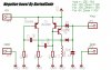
") Also the currents in the above circuit are pretty small, peak is about 200mA in the inductor I think.
Also the currents in the above circuit are pretty small, peak is about 200mA in the inductor I think.
