Continue to Site

Welcome to our site!

Electro Tech is an online community (with over 170,000 members) who enjoy talking about and building electronic circuits, projects and gadgets. To participate you need to register. Registration is free. Click here to register now.

  • Welcome to our site! Electro Tech is an online community (with over 170,000 members) who enjoy talking about and building electronic circuits, projects and gadgets. To participate you need to register. Registration is free. Click here to register now.

555 chip information

Status
Not open for further replies.
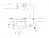
What are the Pos,mot- and neg signifying? (I'm confused by what the arrow breaks are.)
So out of curiosity, does the 555, in simple terms, stretch out a wave form? Sort of like a spark plug?

The 555 is a very versatile building block. In this circuit, it is used as a free-running astable multivibrator with a very asymmetrical duty cycle. It uses a resistor charging a capacitor to create the time delay. Due to internal bias currents and typical capacitor leakage, the timing resistor cant get over 10meg. The bigger the capacitor, the more the leakage, so there is an upper limit on that, too. Practically, a 5min period is about the limit.

When I draw a schematic, I use the "connectors" (what you call arrow breaks) to signify what is on the "circuit board" and what is not. Everything on the left side of the schematic is to be placed on a circuit board; all the stuff to the right is not, but it has to be placed on the page to show how it hooks up, and so that LTSpice knows how to simulate the complete circuit. When you build it, you will not place the motor, diode, or the 12V power supply on the "circuit board".
 
Last edited:
Hi,
I need to create a delay of 0.01 seconds using a 555 Timer. The Timer will receive an input from a relay contact (this is not a constant supply), then wait for 0.01 seconds before giving a one shot output.
Is this an easy circuit to build?
Many thanks for any help.

seema
 
May I ask what it is? It looks like some sort of tilt tray assembly that (based on your request) needs to be tilted once per hour?

I'm really intrigued as to what it does... :)

Could you just run the motor constantly but at a slower speed? All you would need a LM317 adjustable voltage regulator on a heatsink and a pot to fine tune the speed. With a regulated voltage those little DC motors run at a pretty constant speed.
 
Hi,
I need to create a delay of 0.01 seconds using a 555 Timer. The Timer will receive an input from a relay contact (this is not a constant supply), then wait for 0.01 seconds before giving a one shot output.
Is this an easy circuit to build?
Many thanks for any help.

seema

1. What supply voltage?

2. Does the relay contact remain closed while the timer does its thing?

3. What is the duration of the output pulse?

4. Should the timer output be high or low during the output pulse?

5. How long is the relay open before the next cycle?
 
time delay for .o1sec.

1. What supply voltage? : 4.5 v to 6 v

2. Does the relay contact remain closed while the timer does its thing? no

3. What is the duration of the output pulse? .02sec only

4. Should the timer output be high or low during the output pulse?: higher and attched to scr 1a 400v

5. How long is the relay open before the next cycle? .o1sec.
 
Hey mike, could you look over this alteration to your design and tell me the proper way to fix it. What i have done is added a 120v transformer. I was not aware that it changes the design of the caps and all. Also if you'll glance at the differential thermostat that you designed for me for the same alteration. Next time i will know better when i am describing my circuit. Thanks.
 

Attachments

  • motorcontrol1.png
    motorcontrol1.png
    11.3 KB · Views: 300
  • ChrisSolarPump.gif
    ChrisSolarPump.gif
    146 KB · Views: 338
What is egg timer motor running current?

What is water pump motor running current?

What are the transformer specs?
 
What is egg timer motor running current?

What is water pump motor running current?

What are the transformer specs?

Egg timer is 100 ma

The water pump will be 120v run off of a relay with coil voltage of 12v

Specs for the egg timer trans is center tap 6v/6v rated at 12v 450ma
The water pump transformer is a 12v 100ma standard transformer single primary single secondary.
 
This is a an ideal job for a simple PIC microcontroller driving a stepper motor. I started programming from scratch two years ago you will be able to realise your ideas with crystal clock accurracy.

you will have a lot to learn at first but your eventual results will be quicker to make and work better

Don't bother with 555's totally unsuitable for this project. the only way you can realise it is with a board load of logic gates.

P.S. have you thought of using a clock with a 2:1 mechanical divider? the hour hand rotates twice in 24 hours.

Do you have something that i could look at? A schematic of a circuit using this tech you speak of?
It would be nice to explore other techs but i started studying electronics only 2 months ago. I have learn a lot in that time frame. These circuits mikeim has helped me with are teaching me a lot. I am interested in different tech but i am just a newbie. Try not to overwhelm me with complexities, but i do like the challenge.

And as for the clock idea, It needs to rotate 24 times per day which i guess would be the hour hand on a clock. But i don't know how to make that work for a gear motor.
 
Last edited:
Here is a modified version of the Egg Timer. Since the goal is to run the motor off a reduced voltage anyway, I am using the Center Tap on the transformer to reduce the starting voltage to about 8V. The PFet dissipates less power this way. The 555 uses its own diodes and filter cap to keep its voltage more or less constant.
 

Attachments

  • EggTimerT.png
    EggTimerT.png
    42.3 KB · Views: 161
For the water pump, if the pump motor runs on a 12V battery, why do you want to run the timer on a transformer?
 
For the water pump, if the pump motor runs on a 12V battery, why do you want to run the timer on a transformer?

Here is the problem. I was using a 12v pump until it burnt out last month ( after 8 months). I am not willing to spend 230 dollars every year to replace the pump for it to run on 12v to say me 45 dollars in power savings. So i incorporated a 120v circulation pump in it's stead. I pay less than 80 dollars for these pumps, Which pump under pressure, last much, much longer, Are designed for radiant heat systems. I love my solar hotwater system but i have learned that i have to get away from the solar power and focus on the solar collectors, this is where the money is saved. As for now the solar power is a ripoff.
 
Please get me out of the 7404's i can't find one out of the SO-8 type. I need a fet that is TO-220 For simplicity of the homemade design. I don't do surface mount.
 
Please get me out of the 7404's i can't find one out of the SO-8 type. I need a fet that is TO-220 For simplicity of the homemade design. I don't do surface mount.

??????????????????????????? !
 
Please get me out of the 7404's i can't find one out of the SO-8 type. I need a fet that is TO-220 For simplicity of the homemade design. I don't do surface mount.

Try this from the Goldmine.

Through hole is getting hard to find. It is only a matter of time before they will be gone like the dodo...
 
Here is the problem. I was using a 12v pump until it burnt out last month ( after 8 months). I am not willing to spend 230 dollars every year to replace the pump for it to run on 12v to say me 45 dollars in power savings. So i incorporated a 120v circulation pump in it's stead. ...

So you want the circuit to run on a transformer, and switch a relay instead.

Ok, how many Ohms is the relay? What is the relay coil voltage? Is the relay up to switching 120V?
 
So you want the circuit to run on a transformer, and switch a relay instead.

Ok, how many Ohms is the relay? What is the relay coil voltage? Is the relay up to switching 120V?

I have 10 of these to use up.
 

Attachments

  • relay specs.png
    relay specs.png
    32.9 KB · Views: 142
Status
Not open for further replies.

Latest threads

New Articles From Microcontroller Tips

Back
Top