Continue to Site

Welcome to our site!

Electro Tech is an online community (with over 170,000 members) who enjoy talking about and building electronic circuits, projects and gadgets. To participate you need to register. Registration is free. Click here to register now.

  • Welcome to our site! Electro Tech is an online community (with over 170,000 members) who enjoy talking about and building electronic circuits, projects and gadgets. To participate you need to register. Registration is free. Click here to register now.

555 -astable mode

Status
Not open for further replies.

stevez

Active Member
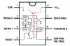
As part of a larger project I used a 555 timer wired for astable operation just as described in National's datasheet. I am using the 'ramp' or sawtooth voltage across the capacitor as my output. My goal was to operate at 30 kHz. I cranked thru the formula a number of times as I fit in parts that I have on hand. I breadboarded the circuit and it worked although at a significantly different frequency - not way off but enough that component tolerances didn't explain it. I convinced myself that the breadboard (an old, low cost one from Radio Shack) was at fault though it would seem that at 30 kHz there should not be a problem. I rebuilt it on a circuit board with similar results. Thru all this I'd look at the ramp voltage - paying attention to the timing more than the actual voltages. Eventually I looked closer at the waveforms.

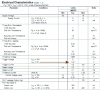
Per the literature and numerous tutorials found on the internet I see that the comparators on the 555 are supposed to charge and discharge the capacitor at 2/3 and 1/3 of the supply voltage. There is little mention of anything else other than some advice on the min and max values for R and C.

My supply was 6 volts - the capacitor was swinging between 4 volts and about 1.75 volts (not 2 volts as expected). If I work backward, using the measured capacitor charge and discharge points, the predicted frequency is right on target.

Now, during all this I had swapped out the 555 thinking there might be a fault and results were similar- though I only measured ramp voltages on the last one. I'm not convinced entirely that there isn't some other obvious fault. C was .001 microfarads, Ra is 22k, Rb is 12k

Thoughts, comments and any insight would be appreciated.
 
I'm slowly turning into mistakeca so please ignor what I said.

At 5V, datasheet shows trigger voltage to be 5/3=1.67V so you should get 2.0 from measurement if Vcc=6V.

I don't know why.
 

Attachments

  • lm555_tr.png
    lm555_tr.png
    10.3 KB · Views: 516
A little theory might help here. Are you familiar with the functional form of the solution of the differential equation that describes an RC circuit? They are exponential functions, and they change at a variable rate depending on how close the capacitor voltage is to the forcing function. The data sheet formulas are approximations that sugarcoat the theory without offering any deeper understanding.

The reason that the 1/3 and 2/3 points are used is because the exponetial functions are closer to being linear there than anywhere else. Close to linear is not the same thing as linear so you still have to do the calculations.

Hope this helps
 
My understanding of the trip point voltages is that they are 1/3 and 2/3 of Vcc, which means they will be the same percentage when Vcc changes and thus the overall timing is not affected.

The 555 would function equally effective with 1/4 and 3/4 trip points voltages if the internal resistors values so determined. However, the 1/3 & 2/3 trip point will be the simplest as it uses three equal value resistors.
 

Attachments

  • lm555_tr1.png
    lm555_tr1.png
    8 KB · Views: 436
Papabravo - at a basic level, I do understand an RC circuit (especially it's not linear behavior) but not enough to have worked all the way to a satisfactory solution. Clearly I missed the trigger voltage point. Back to RC - I am getting some help from a 4th yr EE student. I used to teach him - now he teaches me. Once I explained the behavior to him he explained how I ought to handle it.

I feel like I got a lot out of this exercise. While some might have just swapped parts to get the frequency right I felt that there was something important that I was missing. I did some homework and got some help. I agree with a point that you touched on - simple shortcut formulas. I am a mechanical engineer (and 54) and in my day to day work I take some time to go back and reconcile the differences between shortcut methods that I use for efficiency and raw physics or chemistry. Many of my peers fail to do that and when precision matters they are unprepared.

Anyway, thanks for the help so far.
 
Are you sure tolerance is not a problem?

Passive components have tolerance ratings. The posted tolerance indicates the maximum percentage from the correct value (divided by 2) that the value can be wrong.

For example, if you have a 5% resistor that is 1K, the actual value can be anything from 2.5% below, to 2.5% above.

In this example, the resistor can be from about 975 ohms to 1.025K

Capacitors also have tolerances, but they are generally worse.

These components affect the frequency on a 555, and their values should be double checked. if you need accuracy.

Maybe something you have is broken.
Perhaps you should choose different RC values, so you can obtain a lower capacitor. Why? because the larger value the capacitor, the longer it takes to start.

If you are using electrolytic, try a different type of capacitor.
 
I was surprised not to see more on the trip point issue too, but it may not be something that is significant to many. It may also be that the people who find this important easily recognize the trigger voltage issue. As a hobbyist I am not as alert to this stuff as a pro might be.

I did run calculations to see what would happen if all components were at their tolerance limit and it makes a difference but not all that much. Capacitor used initially was ceramic disc but I switched to silver-mica. I also built it twice on the breadboard and twice on a circuit board with new components.

From now on I can use 15 volts and expect the 1/3 and 2/3 points to work - if I do otherwise I'll have to make some quick measurements and get the heavy duty math out. I'll also watch for this as I work with other ICs and circuits. One "otherwise" might be to run at 5 volts because the trigger point is also stated - 1.67 volts - and do the heavy math to select components. That might help avoid the need to measure.

There's a lot of learning (for me) in stuff like this.
 
Hi stevez,

Sorry I have misled you. You should really get 2.0V because 5V/3=1.67V. Somehow I have difficulty mentally calculating 5/3.

I'll try to do a breadboard of the test and see if the voltage increases with lower frequency of oscillation.
 
Looks like two of us aren't processing 5/3 right!! Good point. And here I thought I understood the source of error - oh well. Now, trigger point is one thing - when the capacitor stops discharging is what I am measuring as 1.75 volts. Maybe there is some switching time that passes between the time the comparator changes state and the capacitor bottoms out.

Again, interesting stuff.
 
Hi stevez,

I have just tested the 555 setup with a 6V supply and component values as per your above test. The frequency is 28.72KHz.

Using a scope, I noted the voltage across the 1000pF capacitor is a typical RC charge/discharge shape and changes within limit of 2.0V & 4.0V, though the output frequency has dropped to 28.10KHz when I attach my 10:1 scope probe to the capacitor.

This seems to agree with the datasheet of 1/3 and 2/3 voltage trip point. Are you measuring the triggering voltage using scope with a 10:1 probe?
 
The scope is set for 1 V/div. I measure exactly 6 V on the supply - having set zero (ground on the AC-GND-DC coupling switch) at the very bottom. That suggests that the probe is 1:1. The scope is a Hitachi, 65 mHz - while not recently calibrated it doesn't seem like there would be that much non-linearity.
 
Not so much as the non-linearity but the input impedance of the scope at 1:1 can be as low as 1M. You could have changed the voltage just by measuring it.
 
eblc1388 said:
Not so much as the non-linearity but the input impedance of the scope at 1:1 can be as low as 1M. You could have changed the voltage just by measuring it.
But loading the timing circuit should not affect the trigger points.
 
RonH - a 0.01 microfarad capacitor is connected from pin 5 to ground. I wondered about that too. I thought it would affect the 2/3 point as well but may have missed something.
 
Ron H said:
But loading the timing circuit should not affect the trigger points.

Yes. I'm wondering about that too. The frequency changed even with a 10M probe but the voltage across the capacitor should be correct.

My test result are fine with a 10:1 probe, so if he does the test again with a 10:1 probe, then I can eliminate the effect of the probe.
 
FYI - frequency is measured with my DMM then verified with timing of the scope. Always checks within reason.

I had thought about using pin 5 to zero in at the end. Somehow that really wouldn't help me understand what's going on.

I am wondering if I shouldn't purchase some new 555s to be certain that they aren't the problem. The ones I've used so far may have been (I am not sure) from one source purchased at the same time. They were in separate packages (Radio Shack) but could possibly be from the same manufacturing lot.
 
For what it's worth I start my test by connecting the DMM. I then add the scope or remove the DMM and chech with the scope. I've not noticed any shift but that doesn't mean it isn't happening.

What I will do though is to use the 10:1 probe just to see what happens.

Thanks for working thru this with me. It's supposed to rain tomorrow -perfect day to tinker a bit on the bench for a bit.
 
Status
Not open for further replies.

Latest threads

Back
Top