Continue to Site

Welcome to our site!

Electro Tech is an online community (with over 170,000 members) who enjoy talking about and building electronic circuits, projects and gadgets. To participate you need to register. Registration is free. Click here to register now.

  • Welcome to our site! Electro Tech is an online community (with over 170,000 members) who enjoy talking about and building electronic circuits, projects and gadgets. To participate you need to register. Registration is free. Click here to register now.

555 & 4017 help please

Status
Not open for further replies.

Icadj

New Member
Thanks to everyone who has helped get me this far.

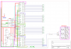
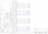
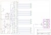
Can someone please check this circuit over and tell me is there any mistakes I need to correct.

The one thing that concerns me is U4 - pin3 - O/P 0 is just connected as an O/P and nothing else or have i missed something.

Yes I know that not all transistors are in the BUT its the only way I could get at least one on the page coz the rest would not fit

Many thanks
Steve
 

Attachments

  • 555+4017x4.JPG
    555+4017x4.JPG
    426.2 KB · Views: 230
  • 555+4017x4.JPG
    555+4017x4.JPG
    502.1 KB · Views: 224
Last edited:
hi,
You cannot drive 7 segment LED's using a 4017, only single LED's as in a chaser display.???
 
Dont want to drive a 7seg display

The idea is to drive rows of LED's to make "lovely" patterns LOL

PS good moring Eric and thanks
 
Dont want to drive a 7seg display

The idea is to drive rows of LED's to make "lovely" patterns LOL

PS good moring Eric and thanks

hi,
OK, its just that you used the 7 segment notation for the LED , ie 1a,b,c,d.....2a,b,c... etc

You do realise that only 1 led will be lit at anyone time thru the sequence?
I will look at your diagram.
 
Just added a second diagram ,,, hope that helps

OH ,,, I see ,,, it was used to get the first page to the second page in the program ,, extending the wires from page 1 to page 2

and i waffle LOL

Thanks Eric
 
Last edited:
hi,
Main connections look OK, removed the 1N914 diode, the LED's are reversed , also dont use pin pin3 Q0 on the 1st 4017 to drive a transistor.

EDIT: It is OK to use pin 3 on the 1st 4017... of course thats got 9 outputs and the remaining 4017 have 8 outputs:eek:
 

Attachments

  • 4017.png
    4017.png
    202.6 KB · Views: 235
Last edited:
Ok many thanks Eric

So lost I've lost O/P 1st 4017, power diode and turn the LED's around.

Please tell me, is it because I'm using the 4017 to drive a transistor at pin3 1st 4017 its not used because going by the data sheet you posted 4 me shows pin3 as an O/P and a resetting next 4017.

many thanks
steve
 
Ok many thanks Eric

So lost I've lost O/P 1st 4017, power diode and turn the LED's around.

Please tell me, is it because I'm using the 4017 to drive a transistor at pin3 1st 4017 its not used because going by the data sheet you posted 4 me shows pin3 as an O/P and a resetting next 4017.


many thanks
steve

Steve,
Read my edit in post #7, I misread a pin!!
 
steve,
I dont know how many LED strings you are planning to attach to each transistor, or the details of the LEDs, but a point you should be aware of is that high current gain of the driving transistor will be as low as 10 or so, when saturated.
So this means that the Base current into the transistor will have to be 10% of the total LED collector current.
Also there is a limit to how much current a 4017 output pins can supply to the Base resistor.

Post a sub section drawing of the LED string and details of the LED's.
 
Eric

Just re-read the post, didnt refresh the page "opps"

Each transistor hopefully would drive a max of 3 strings with a max of 5 LED's in each string.

LED's are 2v2 25mA colour matched from ESR if they have them in stock

I know 2 strings set up the same way will work as I used them on the slowish time you did for me.

thanks
steve

So 5 * 2.2V =11V, you have a 12V supply!.. I would consider a LED current of 20mA.

So the series resistor has to drop 1V at .02A, 1/.02 = 50R
The total collector current will be 60mA, so the base current must be at least 6mA.
 
So i take it thats not gonna work

ref the power-supply, I have pealed off a white sticky back plastic sheet that was on the front of it and found its an old CB power-pack, 3A 13.8v DC. Checking the board it have a varible mini pot which when tweaked gives a voltage with a multimeter of 2.8V - 21.2V.

So setting back to 13.8V , is that gonna help or as I think it might blow everything up as in the chips ,, the current limiting resistor for the LED would have to change to 112 or a 120 which is nearest above the value needed.

Thanks
steve
 
If its a 12V psu it should work OK.?? Puzzled why you think its not going to work??

Just use 47R with the 5 * 2.2V [11v] LED's, if you use 100R's The LED current will be 10mA.
 
Why is there confusion about the schematic for the CD4081 and the CD4017s? The schematic is on the datasheet.

The CD4017s are not reset when power is applied so there will be a few jumbled-up chases until they get into the correct sequence.

The LEDs will be very dim with a current of only 1.6mA if the LEDs are really 2.2V each and the current will be less for the LEDs that are more than 2.2V.

There is barely enough voltage across the current-limiting resistor because there are too many LEDs in series. Then some strings of LEDs will be brighter than others because LEDs do not have a fixed voltage, they have a range of voltages. Therefore instead of 5 LEDs in series use 4 LEDs in series.
They will be brighter if you increase their current to 20mA and USE STANDARD RESISTOR VALUES (500 ohms does not exist).
 
Eric , sorry I understand about wiring I.E. from A to B / C to D etc BUT when you said ,, not to worry
Its the not so finer points of electronic, I dont have a clue about.

The current limiting resistor I got from an online program for working out resistors for LED's ,, Now I am confuzed ,, I see where you get the 20mA LED ,, and ESR are rated at 25mA 2v2 for green but glad I miss read parts as i checked on-line and they are not all the same, 3mm r rated as

Green 2v2 25mA
red 2v0 25mA
yellow 2v1 30mA
but
blue are rated at 4v5 30mA and aprox same brightness

Oh heck UMMMM can we please get back to the 555+4017 and maybe if it works I'll add a single LED to each O/P for now and worry about the trans & LED's after its constructed or does that pose problems.

Thanks for helping me out
Steve
 
Hi there Audioguru, there is confuzion because of my complete lack of understand of how electronics works . Like I said in my last post I understand wiring. Getting the chips right first and asking about LED's + trans is where I got in a muddle.

Any help is always greatfully accepted as long as no one minds putting me right in stages then thats how I'll hopefully learn. Eric has already has been very helpful (with one working circuit) but I lost the plot when it came to LED's coz I haven't got the chips right in my head "yet"

Cheers steve
 
Do u want me to post ESR's catalog in its PDF format
 
Can anyone tell what the maxium width in tracks of vero-board is please. I have a sheet of 36 wide by (lost count) opps ,, and if there's wider where I can get it from

Thanks
steve
 
Simply use Ohm's Law to calculate the LED current;
1) You have a 12V supply.
2) The transistor will saturate with a loss of about 0.1V which can be ignored.
3) The green LEDs might be 2.0V to 2.4V but let us hope that they are all 2.2V.
4) Five 2.2V LEDs in series total 11V.
5) the current-limiting resistor will have 12V - 11V= 1V across it.
6) The value of the current-limiting resistor for a current of 20mA is 1V/20mA= 50 ohms which does not exist. 51 ohms is the nearest standard value.

Because you have too many LEDs in series then their actual voltages are very important.
If their voltages are actually 2.0V then their current will be 39.2mA (when using the 51 ohm current-limiting resistor) and they will soon burn out.
If their voltages are actually 2.4V then their current will be zero and they might not produce any light.

Now try calculating the current with only four LEDs in series.
2.2V LEDs will have a current of 20mA when the current-limiting resistor is 160 ohms.
If the LEDs are actually 2.0V then their current will be 25mA.
If the LEDs are actually 2.4V then their current will be 15mA.
This is much better than them burning out or not lighting.

Note that modern very bright green LEDs are about 3.5V each like blue and white LEDs are.
 
Status
Not open for further replies.

Latest threads

Back
Top