Arkham00
Member
Today, 3-wire fan are very common in computers. Two pins are for the power supply and one is for the speed feedback as an open collector circuit.
If I want to use a PWM to control fan speed and still have speed feedback, how do I connect the driving transistor? On the +V side or on the -V side of the fan?
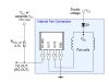
Here is a circuit of the internal circuit of a 3-wire fan taken from a web site
**broken link removed**
If I connect, let's say, +V do +5Vdc and -V to the collector of an NPN transistor (whose emitter is to GND) driven by the PWM of a microcontroller, even if I connect "tach out" to an input, the micro will not be able to read the speed beacause the hall-effect switch will be continuosly powered on and off by the pwm.
Maybe that schematic is wrong but I'm not able to understand how to control fan speed with a PWM and still read the speed pulses.
If I want to use a PWM to control fan speed and still have speed feedback, how do I connect the driving transistor? On the +V side or on the -V side of the fan?
Here is a circuit of the internal circuit of a 3-wire fan taken from a web site
**broken link removed**
If I connect, let's say, +V do +5Vdc and -V to the collector of an NPN transistor (whose emitter is to GND) driven by the PWM of a microcontroller, even if I connect "tach out" to an input, the micro will not be able to read the speed beacause the hall-effect switch will be continuosly powered on and off by the pwm.
Maybe that schematic is wrong but I'm not able to understand how to control fan speed with a PWM and still read the speed pulses.