10W from the 2N3055?
When a 2N3055 is turned on hard, its collector to emitter voltage produces a max saturation voltage loss of about 0.4V when its collector current is about 1A and its base current is 100mA. Then with a 13.2V supply, an 8 ohm speaker gets (13.2V - 0.4V)/8 ohms= 1.6A and its power for half the time is (1.6A squared x 8 ohms)/ 2= 10.2W. If 555 #2 is good then it can produce about 103mA into the 100 ohms resistor in series with the base of a 2N3055 and the output of the 2N3055 into the speaker might be only 1A instead of 1.6A so the power in the speaker will be only 4W.
Guess what? The 1kHz and 1.5kHz is a squarewave that produces only 2W to 5W. The high frequency harmonics produce the other 2W to 5W that maybe the speaker or your hearing cannot produce.
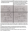
The output of the 2N3055 is not push-pull so DO NOT USE A SERIES CAPACITOR FROM THE 2N3055 TO THE SPEAKER!
If you used a push-pull audio amplifier and it produces sinewaves, not badly distorted squarewaves like a 555 does, then a coupling capacitor blocks DC and low frequencies and is needed when there is a single polarity supply. The speaker voltage swings positive and negative because the coupling capacitor stays charged at half the supply voltage.
But the capacitor feeding the speaker is a highpass filter that cuts off low frequencies. There is a simple formula to calculate the cutoff frequency of a coupling capacitor feeding a certain load impedance.
A 470uF capacitor feeding an 8 ohm speaker cuts 43Hz to half the power (-3dB) of much higher frequencies and the 0.1uF capacitor you guessed about cuts radio frequencies higher than the AM broadcast band and less. The middle of the AM band would be at 1/5th the max power, ultrasonic squeaks from bats would be at a fairly low level and audio sounds would have levels lower than you can hear.