Electro Tech is an online community (with over 170,000 members) who enjoy talking about and building electronic circuits, projects and gadgets. To participate you need to register. Registration is free. Click here to register now.
Welcome to our site! Electro Tech is an online community (with over 170,000 members) who enjoy talking about and building electronic circuits, projects and gadgets. To participate you need to register. Registration is free. Click here to register now.
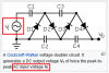
Is there a better DC to AC circuit than this? 35 years ago when camp grounds had no electricity I built this to run 3 light bulbs 25w each transistors and resistors make too much heat. This could be used to make 46vAC x 1.414 = 65vDC
That old inverter circuit has problems:
1) The polarity of the capacitors is backwards. The base voltage is +1V max but the collector voltage is +24V max.
2) Each 180 ohms base resistor has 11.2V across it which provides a base current of only 11.2V/180 ohms= 62mA. Then each transistor saturates with a maximum output current of only 0.62A. The output power is zero because all the power is wasted in each 10 ohms resistor.
3) The maximum allowed reverse base-emitter voltage is shown in the datasheet to be 7V but in this circuit each capacitor charges to about +23V then tries to drive the base to -23V which causes avalanche breakdown, damaging the transistors.
Years ago I fixed it on Arron Cake's website:
1) I corrected the capacitors polarity and increased the value to 270uF to match the reduced values of the base bias resistors.
2) I reduced the base bias resistor values to 47 ohms. I increased the value of the 10 ohms resistors to 220 ohms.
3) I added a diode in series with the base of each transistor and added a 2.2k resistor from each base to ground.
The output power of the fixed circuit is 20W with a sagging output voltage.
I have a simple multiplier circuit That works I used it to make 30,000.v from 600v. I have seen small 3 & 4 stage multipliers in other circuits so that made me think maybe 3 or 4 stages could increase 13v battery voltage to about 60 volts. I know these are not very efficient it would be interesting to build it just to see if I can get a voltage higher than 13v.
A re-entrant horn speaker focusses sounds in one direction making it louder.
A real power of 50 Watts is 100 peak Watts.
A siren powered with a charging car battery at 14.4V is louder than when the battery is at only 12V.
I have seen small 3 & 4 stage multipliers in other circuits so that made me think maybe 3 or 4 stages could increase 13v battery voltage to about 60 volts.
I remember using those multiplers on AC circuits not DC. Your right it won't work this DC circuit. I should work if I add another 555 just to make 60Hz or 400Hz for the multiplier. But it will not help on the AA battery pack it produces only 12v x 2a = 24w. It might help increase power using a car battery to produce more power for the 2N3055. This is a learning project for me it would be interesting to build the multiplier to see if it works but not sure I will I don't really have a use for a siren. Now I am curious to know if a 555 circuit 60 Hz or 400 Hz will make 48v or 60v from 12v? I believe each stage of the multiplier increases voltage by the value of the power supply 12v x 5 = 60v
Somewhat less than that because of voltage drops across the diodes.
Even if you get the voltage up, the current will be limited by the charge storage capacity of the capacitors, so might not be as much as you'd like.
Somewhat less than that because of voltage drops across the diodes.
Even if you get the voltage up, the current will be limited by the charge storage capacity of the capacitors, so might not be as much as you'd like.
I knew there will be a voltage drop but don't recall how much 1v or 2v per diode? That info is probably on the data sheet. I have built marx generator and other high voltage generators caps need to be sized correctly for the diodes, if caps are too large it blows the diodes or caps all need current limiting resistors. If I use 1N4007 diodes they are 1a if I get 60v to the 2N3055 = 60w but my experience with this voltage multiplier it probably can not produce a full 60w quick enough they were always slow to fully charge up. When I stepped up 600v to what every it was I did 20KV or 30KV don't remember it produced a spark about 1 time per second. Some where I read once the rate multiplier charge up according to the number of stages it did not seem very important at the time working with HV there was no time limit requirement but it probably is more important for an amplifier that needs continuous power. 1 or 2 or 3 stages might actually work for a 2N3055 amp.
OK. Older CRT used a "tripler". The tripler took the output for the line transformer...and tripled it. So 7.5kv out from the line transformer was equal to around 22.5kv from the tripler.
Gary...you are confusing CRT HV with other stuff here.
Speakers are designed to be fed AC but your single 2N3055 is not push-pull so it feeds DC pulses. An audio amplifier produces AC. When your DC pulses feed a speaker then the power must be 1/4 the speaker's rating.
Your idea of using a 60V supply will produce 60V/8 ohms= 7.5A pulses. The average output power is (60V x 7.5A)/2= 225W! A 100W 8 ohm speaker maximum peak input voltage is only 40V. Any more voltage will cause the voice coil to smash against the magnet structure causing damage.
I wonder what is the jail sentence for somebody who is disturbing the peace with an illegal siren?
This site uses cookies to help personalise content, tailor your experience and to keep you logged in if you register.
By continuing to use this site, you are consenting to our use of cookies.