Sounds like you are going to have a pretty comprehensive electronics/mechanical workshop. I am hoping to do some physical when our other house is refurbished and we move in. The present house has no room for a decent workshop.I have been collecting various bits. I have about 2000 0.25W resistors but only a few caps mainly ceramics. I have just about enough to make a couple of little LM317 regulators with variable pots.
I sent away for and have :- heat shrink (a lot different sizes) , 5 prototyping board (just circular copper pads), a 4 digit V & A meter, an assortment of LMXXX and not much more. I saved a lot of the coloured wire from the PC power supplies.
I am going to send away - my second order to Banggood - for 10 pairs of leads with crocodile clips (I only have 2), 10 pairs of banana plugs and sockets, a selection of fuses, fuse holders. 2 cheap V & A meters for the 4A 20V thing, 10 knobs with 1 - 10 on them. Banggood also have a rotary switch that looks OK.
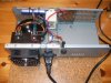
Modular is good, and there is no reason why the transformer, rectifier, and res capacitor cannot be in a separate case, providing there are thick wires between the rectifier case and the voltage regulator case. But, I am afraid that it would be unwise to separate the functions further. The reason is that long wires can induce frequency instability and compromise the PSU performance. In fact the layout, of the power transistors and the controlling electronics is critical- sorryI was going to make this thing roughly modular. The transformer, rect. for the 36V and 12V (fans and meter supply) are in one case. This is up and running. Attached to this is the second case for the regulator heat sinks. I think I will have to take it apart and rebuild with a third one on the end. No 'walls' between them. It's held together on 15mm aluminium channel underneath. It looks better than it sounds.
Photos would be good- no need to start a new thread. Photos of your PSU will be in the context of this thread.Should I add some photo's and maybe we should start a new thread?
")
The circuit of post #58 is very simple to understand and is normally well behaved (famous last words). There have been thousands of similar circuits built.I have just seen your latest circuit.
I wanted variable Amps but didn't like to ask for it.
I was fine until I saw the words 'negative regulator'.
A negative three terminal regulator (TTR) is exactly the same as a positive TTR that you are familiar with, except the polarity of all voltages are reversed. The LM337 TTR is the negative version of the LM317 TTR.
Good move. The hardware is the critical area, in my opinion.I'll concentrate my thoughts on the hardware...
Conductors are other items that can never be too big, from an electronic point of view. Ordinary heavy gauge wire, around 14 SWG to 18SWG will be fine for the heavy current paths. The way that the wires connect is also important, especially to ensure good current sharing between the power transistors.When you say 'massive conductors' do you mean the sort of wire in a PC PSU - 20A stuff or are we talking copper busbars.
Will do.If you could possibly add a few 'for example' names to the components it might help me look that type up and understand a bit more. I understand everything is up in the air - just a rough idea might help.
spec
Last edited:
 I did! (see post #49)
 You are not ex Royal Navy are you?