Continue to Site

Welcome to our site!

Electro Tech is an online community (with over 170,000 members) who enjoy talking about and building electronic circuits, projects and gadgets. To participate you need to register. Registration is free. Click here to register now.

  • Welcome to our site! Electro Tech is an online community (with over 170,000 members) who enjoy talking about and building electronic circuits, projects and gadgets. To participate you need to register. Registration is free. Click here to register now.

2n2222/tip120

Status
Not open for further replies.

kimbear

Member
Can a tip120 be used to replace a 2n2222 (taking into consideration the different pinout configurations) when driving a bank of leds from a microcontroller??
Thanks in advance
 
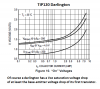
For driving a set of LEDs from a 3.3 or 5V logic-level uC signal you *should* be fine. Just keep in mind that because the TIP120 is a Darlington pair transistor, it has a Vbe forward voltage of 1.4V rather than the 2N2222's 0.7V, and may have a higher gain than the 2N2222, so be sure that you are properly limiting the current to the LEDs if you weren't already doing so.

It's not a 1:1 replacement per se, so depending on the configuration there may or may not be issues. We would probably need to see a schematic to be sure.
 
The TIP120, when turned on hard, will have a collector to emitter voltage loss of 0.7 volts.
The 2N2222, when turned on hard, will have a C-E voltage loss of 0.2V.
 
"The TIP120, when turned on hard, will have a collector to emitter voltage loss of 0.7 volts."

Incorrect.

The collector-emitter voltage across a Darlington transistor is always more than 1.4v and can be as high as 2v to 4v.


"and may have a higher gain than the 2N2222, so be sure that you are properly limiting the current to the LEDs if you weren't already doing so."

This is a technically false statement.
Both transistors will be turned on fully and it is just the voltage between collector-emitter that has to be taken into account.
 
Incorrect.
The collector-emitter voltage across a Darlington transistor is always more than 1.4v and can be as high as 2v to 4v.

You need to do a introductory course on transistor operation, your post is incorrect and misleading.
 

Attachments

  • A003.gif
    A003.gif
    24.1 KB · Views: 236
"and may have a higher gain than the 2N2222, so be sure that you are properly limiting the current to the LEDs if you weren't already doing so."

This is a technically false statement.
Both transistors will be turned on fully and it is just the voltage between collector-emitter that has to be taken into account.

That relies on the assumption that the transistor is going into saturation and that the current is being limited at the collector side, hence my original statement about limiting the current if they weren't already. We have been shown no schematic, so if the OP were doing something like, say, limiting the base current to control the LED brightness, then the transistor would not be going into saturation, and the Vbe and gain would come into play. That's not necessarily the recommended way to do that, of course, but I felt the need to cover multiple possible configurations.
 
Last edited:
The collector-emitter voltage across a Darlington transistor is always more than 1.4v
upload_2017-2-22_6-56-26.png

From data sheet. Vce =
and may have a higher gain than the 2N2222
We don't know the current. Because both transistors are to do the same job (replacement) then I will assume low current. The graph for the TIP120 shows a gain of 475 at 100mA. At lower current, lower gain. This part was designed to run at 2A.
upload_2017-2-22_7-0-48.png

The 2N2222A has a gain that peaks at 150mA in the range of 100 to 300. You are right about gain. I wanted to show that when you use a large transistor out side of it intended range it does not work well. (even a Darlington)
 
Why argue about it when the datasheet shows the saturation voltage drop?
 

Attachments

  • TIP120 darlington Vce.png
    TIP120 darlington Vce.png
    37.2 KB · Views: 274
Status
Not open for further replies.

New Articles From Microcontroller Tips

Back
Top