Continue to Site

Welcome to our site!

Electro Tech is an online community (with over 170,000 members) who enjoy talking about and building electronic circuits, projects and gadgets. To participate you need to register. Registration is free. Click here to register now.

  • Welcome to our site! Electro Tech is an online community (with over 170,000 members) who enjoy talking about and building electronic circuits, projects and gadgets. To participate you need to register. Registration is free. Click here to register now.

Only works with 2n2222 Why ?

Status
Not open for further replies.

DICKB

New Member
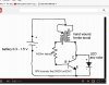
In the circuit shown in the attached image I am using a ferrite core wound with approximately 40 turns and center tapped .

I'm using a 1.5 volt battery and a white led.

The circuit is shown with a 2n3904 or a bc547.

I found the circuit on you tube at https://www.youtube.com/watch?v=pu1UlF5Owpk

The led does not light when I used either 2n3904 or bc547 but works fine with a 2n2222

Can anyone explain why ??

Thanks
 

Attachments

  • Joules thief.jpg
    Joules thief.jpg
    43.5 KB · Views: 229
Likely the gain of the particular 2N2222 you are using is higher than the other transistors.
 
Try more transistors. I'll bet you find some 3904s that work and some 2222s that don't.
 
I would have expected the LED to be in series not in parallel. How comes?
 
Last edited:
I would have expected the LED to be in series not in parallel. How comes?
The idea if this circuit is that the battery does not have enough voltage to drive the LED direct. The circuit 'boosts up' the voltage until the LED turns on.
 
I'd suggest replacing the fixed 1KOhm with a rheostat.
I'm guessing that playing a little bit with the rheostat, you could compensate for the differences in the transistors.
 
This is the kinda job our techie ()blivion would be able to answer. However, according to him, Kaparnik's circuit is quite inefficient and it has a good chance of destroying the LEDs. ()blivion made another improved version like this:Finalized.jpg

In case you want to try this one out as well. :)
 
Here is the Makezine article:
 

Attachments

  • makezine joule thief.png
    makezine joule thief.png
    67.1 KB · Views: 171
Hi all.

Thanks for the plug Vizier87. Though I would like to point out that many many people here are as much or more skilled than I am, some even in this thread. All I have is experience and knowledge in the area. With that particular project, I had a light bulb of an idea, and I just focused my effort in to it. The image you have was the result. But It could have been anyone probably.

Kaparnik's circuit is quite inefficient
The original "Joule Thief" circuit is plenty efficient, it's the reason I chose it for my project. It's actually one of the most efficient of the simple converters out there. That's why it's so popular. My only beef with it was that, in it's basic form, it is totally unregulated and easily capable of destroying LED's and other things if you are not careful. So I added regulation. My circuit is, in theory, just as efficient as the original, as it uses the original in whole as the core.

To the OP and his problem.
The advice that has been given so far is all good stuff. There is little else I could add.

If I added anything to the conversation, I would wonder if you didn't get the pins mixed up, since it hasn't been suggested. I can't count how many times I have miswired a project by forgetting that some times the TO92 package are ECB pin order instead of EBC pin order, or even CBE. Make sure you have this checked and accounted for along with everything else mentioned.

The 2n2222 and the 2n3904 both use EBC pin order when looking at the flat side, but the bc547 looks to use the reverse order.

Anyway, good luck.
-()b
 
Hi all.

Thanks for the plug Vizier87. Though I would like to point out that many many people here are as much or more skilled than I am, some even in this thread. All I have is experience and knowledge in the area. With that particular project, I had a light bulb of an idea, and I just focused my effort in to it. The image you have was the result. But It could have been anyone probably.


The original "Joule Thief" circuit is plenty efficient, it's the reason I chose it for my project. It's actually one of the most efficient of the simple converters out there. That's why it's so popular. My only beef with it was that, in it's basic form, it is totally unregulated and easily capable of destroying LED's and other things if you are not careful. So I added regulation. My circuit is, in theory, just as efficient as the original, as it uses the original in whole as the core.

Thanks for pointing it out. I see. I want to rebuild mine soon. :)
 
Status
Not open for further replies.

Latest threads

Back
Top