Continue to Site

Welcome to our site!

Electro Tech is an online community (with over 170,000 members) who enjoy talking about and building electronic circuits, projects and gadgets. To participate you need to register. Registration is free. Click here to register now.

  • Welcome to our site! Electro Tech is an online community (with over 170,000 members) who enjoy talking about and building electronic circuits, projects and gadgets. To participate you need to register. Registration is free. Click here to register now.

25.6Vac to 24VDC

Status
Not open for further replies.

PhillDubya

New Member
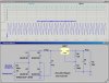
I have got a circuit that needs right at 24v dc. Its actually a load cell that is accurate to .1lbs. So 24V right on the dot is actually important.

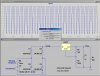
So I have a transformer that is roughly 25.6vac out. I am using a an LM317 voltage regulator with: R2=1800 Ω, and R1=100 Ω.

From the formula: Vout = 1.25V(1+(r2/r1)) and thus: if R1= 100 Ω --> R2 = (24V/1.25V-1)100Ω = ~ 1800Ω.

However, from that I am getting like 17V???

Any idea why? Or what resistor combination I might use?

Edit: I understand that there is some tolerance associated with non-precision resistors, but 17V?????:confused:

Thanks
 
Last edited:
You need a bigger transformer or change your bridge. Your to close to the volts you want
If you want 24 volts dc
A 25.6 volt transformer two tap is good for about 12.8 volts dc
 
Last edited:
Measure the voltage at the input to the LM317 with a scope. At the lowest point of the ripple it needs to be > 27V.

Full-wave rectification?

Size of the filter capacitor between the rectifier(s) and the input to the 317?

How much current are drawing from the 317?
 
A full-wave bridge rectifier would give you about 35 volts dc from your transformer then put
Size of the filter capacitor between the rectifier(s) and the input to the 317
 
Last edited:
Your 25.6vac is plenty - if not too much. It's getting close to the maximum for the 3-terminal regulator.
However, if your output voltage is not high enough, simply change one of the resistors. You can change either.
Putting another resistor across one of them will increase the output voltage.
This is for you to experiment with.
Make sure you have a 0.1u on both sides of the regulator (close to it) and an electrolytic on both sides.
Put a small load (via a resistor) on the output. Make sure the leads to the regulator are short.
Feel the regulator to see if it is getting hot.
Do you have full wave rectification. Feel each diode. How much current are you drawing?
Try another regulator.
Measure the AC voltage again with another meter.
Measure the DC voltage again with another meter.

In addition, if the 26v AC is a "marking" on the transformer, it will be up to 5v higher than this so that the voltage drops to 26v AC under load. You could be reaching or exceeding the max for the regulator.
 
Last edited:
As the others said, yoy have to increment the input voltage. To get rid of the resistor problem, simply use a variable pot attached to the LM317, and when you get the desired voltage you can

1. jam the pot to set it permanently on that position
OR
2. remove the pot, measure its resistance and put the equivalent resistor in its place
 
Last edited:
A full-wave bridge rectifier would give you about 35 volts dc from your transformer

Minor nit: a full-wave bridge rectifier behind a 25Vrms transformer winding would produce a ripple waveform which is about 23.5Vrms. (you lose two diode drops in the process).

Only by capturing the full-wave rectified peaks in a large capacitor at low load current do you get something like 1.3 times the transformer voltage, i.e. about 33V, which drops rapidly as the load current increases. That is why you need a regulator. The "valley" of the ripple cannot go below the LM317's dropout voltage, in the O.P.'s case, 24+1.8V≈26V
 
his is for a lm317
Typical Application

Output Current 1500, 1000, 500 mA
Input Min Voltage 4.2 Volt
Input Max Voltage 40, 37 Volt
Adjustable Output Yes
On/Off Pin No
Error Flag No
Temperature Min -40, 0 deg C
Temperature Max 125 deg C
RegType Linear Regulator
 
Last edited:
Mike I did the math and a full wave bridge will give you a little over 35volts dc from a 25.6 volt ac transformer if he size a capacitor the right size to filter it out before his LM317 then set it with a pot to the 24 volts he will be good to go
 
Close to 33 with a 50mA load and a 47uF filter cap. See V(unreg). The complicated expression plotted in the lower plot pane is the power dissipated in the LM317. If the O.P. forgot to put a large heatsink on the 317, it is going into thermal shutdown, and that is why the voltage is low...
 

Attachments

  • 24VPowerSupply.jpg
    24VPowerSupply.jpg
    276.1 KB · Views: 208
It is only the difference between the input voltage and the output voltage multiplied by the current, that creates the wattage lost in the regulator. That's why a regulator can output a high current when the output voltage is high, but must be de-rated when the output voltage is LOW.
 
Mike I did the math and a full wave bridge will give you a little over 35volts dc from a 25.6 volt ac transformer if he size a capacitor the right size to filter it out before his LM317 then set it with a pot to the 24 volts he will be good to go
I suspect that PhillDubya doesn't have a filter capacitor after the rectifier at all. :rolleyes:
 
Last edited:
I suspect that PhillDubya doesn't have a filter capacitor after the rectifier at all. :rolleyes:

I reran the sim without the filter cap, and look what the average voltage is :D
 

Attachments

  • 24VpowerSupplyNoFilt.jpg
    24VpowerSupplyNoFilt.jpg
    277 KB · Views: 196
OK.

MikeMl said:
I reran the sim without the filter cap, and look what the average voltage is

kchriste said:
I suspect that PhillDubya doesn't have a filter capacitor after the rectifier at all.


I am a noob. Yes, I forgot the filter cap. After putting a 47uF filter cap, I am now getting roughly 23.7v which is what I need.
:eek:

Thanks a lot. Even though I am usually very abruptly reminded of my mistakes here I can always count on the accuracy of the help.

Seriously, thanks a lot for your time, all of you who posted here.
:)
 
Last edited:
Mike that sim looked right it matched what i figured all but 33 volts. But I never used a sim I aways build what i need. looks good . but whats 2 volts lol
 
Last edited:
OK.

I am a noob. Yes, I forgot the filter cap. After putting a 47uF filter cap, I am now getting roughly 23.7v which is what I need.
:eek:

Thanks a lot. Even though I am usually very abruptly reminded of my mistakes here I can always count on the accuracy of the help.

Seriously, thanks a lot for your time, all of you who posted here.
:)

Not Sure What your Load Current is? But I would Recommend a Bigger Capacitor to Eliminate AC Ripple and Beter Stabalize the Ouput.

Possibly 470uF or More.
 
Last edited:
Your 25.6vac is plenty - if not too much. It's getting close to the maximum for the 3-terminal regulator.
Snip
In addition, if the 26v AC is a "marking" on the transformer, it will be up to 5v higher than this so that the voltage drops to 26v AC under load. You could be reaching or exceeding the max for the regulator.
Actually he isn't getting anywhere near the voltage rating of the regulator.

Remember the LM317 is a floating regulator so it doesn't see the 0V rail, it just sees the input-output voltage. You've forgotten that it's only the input-output voltage that really matters. With 24V out, the input voltage can safely be as high is 64V so even if the transformer puts out 45V off load, it won't matter.

The only potential concern is short circuit protection and capacitive loading on the output of the regulator. If the output is shorted and the input voltage >40V then the regulator might be damaged. If the input voltage rises sufficiently faster than the voltage on the capacitors connected to the output or a large capacitance is suddenly connected to the output, the LM317 could suffer the same fate.

Input-output transient protection can be provided by adding a high power zener 39V diode between the input and output terminals and short circuit protection can be re-instated by adding a fast blow fuse.
 
Last edited:
Status
Not open for further replies.

Latest threads

New Articles From Microcontroller Tips

Back
Top