Continue to Site

Welcome to our site!

Electro Tech is an online community (with over 170,000 members) who enjoy talking about and building electronic circuits, projects and gadgets. To participate you need to register. Registration is free. Click here to register now.

  • Welcome to our site! Electro Tech is an online community (with over 170,000 members) who enjoy talking about and building electronic circuits, projects and gadgets. To participate you need to register. Registration is free. Click here to register now.

220 volt double pole breakers (US)

Status
Not open for further replies.
The article confused things by saying "The neutral connection is provided to prevent an open circuit from shutting down power to everything in case of a failure in one branch. It provides an either/or path."
Yes, that's true, but not the most important function which is to SOLIDLY ANCHOR THE SYSTEM TO A 0V (GROUND) REFERENCE POINT.

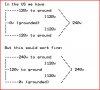
The neutral would have zero current only when the load on both 120v legs it equal, which generally is never the case. Any imbalance FORCES current flow on the neutral. Since the neutral is solidly tied to the center tap of the winding (and ground) it has to stay at the 0 volt potential, but the result is current flow on the neutral equal to the DIFFERENCE between the two legs. Kind of like how a zener diode regulates voltage, once the zener voltage is reached, the potential cant climb any more, the harder the circuit tries to drive the potential up, the more current the zener has to pass.
 
BTW,
The choice to ground the center tap was made to limit any point in the system to a max of 120V above earth (ground) potential. 9 out of 10 times when someone receives a shock it's ground to phase, not across the entire winding.

In the US we have;

Edit: <snip messed up drawing> See next post.......

It would just be more dangerous if you happen to touch the higher leg.
 
Last edited:
Trying again

Edit; I don't know WTH the problem is with ASCII art on this forum engine but it looked right when I posted. The engine doesn't like white space apparently. See attached...
 

Attachments

  • split.JPG
    split.JPG
    40.1 KB · Views: 1,030
Maybe a schematic will help make it clear. It shows two 120V legs, with one circuit each (1 breaker and 1 load per leg), and a 240V circuit with a 2-gang breaker and load.

housecircuit-gif.35486


So, basically a 120V circuit is between one side of the transformer secondary and neutral (center tap). A 240V circuit is across the entire transformer secondary, the center tap doesn't come into play (except indirectly via safety grounding). The neutral is connected to ground at the panel.
 

Attachments

  • housecircuit.GIF
    housecircuit.GIF
    6.6 KB · Views: 3,266
Last edited:
The neutral return current is confusing to a lot of licensed electricians.

When wiring a house, the installer distributes the 120 vac loads, which are light fixtures and outlet sockets to try and balance out the possible 120vac loads on each half of the 'transformer'. Breaker panels do a swap of L1 & L2 phases (the ends of 240vac transformer) for every other breaker position down a vertical row.

In reality the random useage within the house determines how much load is on L1 or L2 phase.

Now for example, If the 120vac loads where exactly equal on L1 & L2 phases to neutral, there would be no neutral current on the neutral line back to the transformer.

Now for a more realistic example, say all the 120vac lights, hair dryer, TV's, etc. turned on resulting in 120 vac loads of 20 amps on L1 side of transformer and 30 amps on L2 side of transformer. There would be 10 amps of current on the neutral line back to the transformer center tap.

240 vac loads like central air conditioner, water heater, clothes dryer, and cooking range create no neutral current as they are directly across the L1 and L2 connections.

Then there is power factor and what it does to current, but we'll leave that for another day.
 
Last edited:
Thanks guys, the neutral current thing still bugs me a little, but I do see how grounding the neutral helps the system stability and balance.

I do have another thought to parse, but I'll issue that question tomorrow.

I can't believe I had this wrong all this time, and I find it amazing how many electrically qualified people I know are unclear on this. Just today I described it to three electrically qualified coworkers and only one, the refrigeration specialist, knew how it worked.

I find it interesting how we can learn specialized knowledge about the electrical/electronics field and always find gaps in areas where we are less familiar.

I wonder if any of the older, more seasoned experts on the forum can admit learning something that might be considered fundamental by some late in their careers :)
 
I have been an electrical engineer for 35 years. I have designed RF and power management circuits.

I know about design of switching power supplies and specifically how a pulse width modulated switcher is used to create a sinewave inverter.

A month or so ago I noticed a picture on the web of the inside of one of the sinewave inverters that are for commercial connections to power grid. There was a large conventional looking silicon-iron E-I core 60 Hz transformer but no large torroid coils or capacitors normally used to filter the high frequency PWM into a clean 60 Hz sinewave.

When I specifically asked why no filter, one guy responded that designed that type of inverter and explained the new trick was to select the right alloying of the transformer core and the right switching frequency of the PWM and the transformer can double as filter choke for the high frequency PWM, resulting in clean 60 Hz sinewave out of the transformer. No extra input PWM filter chokes needed to remove the high frequency PWM waveform.

You do have to deal with a lot of 'frogs' for every 'prince' bit of info you find. Then there is the forum's grumpy bridge troll. Every forum has at least one of them resident.
 
Last edited:
ke5, electronics and electricty in general is a virtually infinite field. Everything from electronics as we understand them (modern electrical devices) all chemical reactions, and even friction and the fact that matter can't pass through other matter is all due to the electron. Despite what we appear to understand as mass if electrical interactions weren't occurring we could easily pass through solid objects, on the molecular and atomic level gravity can almost be disregarded as it's not really important compared to electron interactions.
 
A month or so ago I noticed a picture on the web of the inside of one of the sinewave inverters that are for commercial connections to power grid. There was a large conventional looking silicon-iron E-I core 60 Hz transformer but no large torroid coils or capacitors normally used to filter the high frequency PWM into a clean 60 Hz sinewave.

When I specifically asked why no filter, one guy responded that designed that type of inverter and explained the new trick was to select the right alloying of the transformer core and the right switching frequency of the PWM and the transformer can double as filter choke for the high frequency PWM, resulting in clean 60 Hz sinewave out of the transformer. No extra input PWM filter chokes needed to remove the high frequency PWM waveform.

Thats basically all there is to it some times. Why over complicate a control circuit when you can just use the good old laws of physics and some properly chosen components to get the same or even better end results and often for far less investment in time and materials.
 
Status
Not open for further replies.

Latest threads

New Articles From Microcontroller Tips

Back
Top