Working on that George,
I just migrated the whole code to an 18F4525 to see if I could actually do it..
Its working minus the DS18S20. and I think its the driver code.
One quick question for you George,
Did you create your own digits or use a manufactured one.
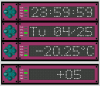
Reason I ask is the code as it sits has no room for a negative sign, My solution at this point is if your made your own digits as I did, then using the DP (dot) from the left digit can become your negative symbol. just series 2 or 3 led's with resistor and you can at least have the hardware ready.
I just migrated the whole code to an 18F4525 to see if I could actually do it..
Its working minus the DS18S20. and I think its the driver code.
One quick question for you George,
Did you create your own digits or use a manufactured one.
Reason I ask is the code as it sits has no room for a negative sign, My solution at this point is if your made your own digits as I did, then using the DP (dot) from the left digit can become your negative symbol. just series 2 or 3 led's with resistor and you can at least have the hardware ready.
")