Continue to Site

Welcome to our site!

Electro Tech is an online community (with over 170,000 members) who enjoy talking about and building electronic circuits, projects and gadgets. To participate you need to register. Registration is free. Click here to register now.

  • Welcome to our site! Electro Tech is an online community (with over 170,000 members) who enjoy talking about and building electronic circuits, projects and gadgets. To participate you need to register. Registration is free. Click here to register now.

verilog, verilogger, file with 'v' extension

Status
Not open for further replies.
Thank you.

I'm trying to write a code for D flip-flop but I'm getting one error. Could you please help me with it? I understand that there would be many other easier ways to do this code but I'm trying to write my own code as much as possible.
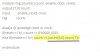
Error:
err2-jpg.86295


C:
// Clock
module clock_10();

  integer clk;

  always begin
  clk = 0;
  #10  clk = 1;
  #10;
  end

  endmodule


//D Flip-Flop
  module D_flip_flop(Q_out,D_data,clk);

  input clk;
  input D_data;
  output Q_out;
  reg Q_out;

  always @(posedge clk)  begin
  Q_out <= D_data;
  end

  endmodule

// Stimulus

  module testbench;

  reg D_data;
  reg clk;
  wire Q_out;

  D_flip_flop d_flip_flop(Q_out,D_data,clk);

  clock_10 clk;                                            //line #47

  initial
  begin
  D_data <= 1;
  #25 D_data <= 0;
  #45 D_data <= 1;
  #65 D_data <= 0;
  #50 $finish;
  end
  endmodule
 

Attachments

  • err2.jpg
    err2.jpg
    3.8 KB · Views: 213
Last edited:
Well obivously you cannot have an instance called clk and at the same time have a wire called clk. How do you expect the compiler to makes any sense of which is which?
Or I may be wrong and it expects you to pass the inputs and outputs to the instance, but still it is a bad idea to call enitrely different things the same name. Why don´t you just put the always block that generates the clock inside the testbench module?

And by the way, why would you instantiate something that doesnt have any outputs? That would not make any sense.

Maybe you should have each module in its own file, this way you will get better hang on how the hierarchy and namespaces behave.
 
Last edited:
Thank you for the suggestion. I have updated the code as follows.

C:
module D_flip_flop(Q_out,D_data,clk);

  input clk;
  input D_data;
  output Q_out;
  reg Q_out;

  always @(posedge clk)  begin
  Q_out <= D_data;
  end

  endmodule

// Stimulus

  module testbench;

  reg D_data;
  reg clk;
  wire Q_out;

  D_flip_flop d_flip_flop(Q_out,D_data,clk);

  always begin
  clk = 0;   
  #10  clk = 1;
  #10;   
  end

  initial
  begin
  D_data <= 1;
  #25 D_data <= 0;
  #45 D_data <= 1;
  #65 D_data <= 0;
  #50 $finish;
  end
  endmodule
 
Hi

I was trying to write a code for serial in/serial out 4-bit shift register. But I'm getting an error and besides that I also don't really know if the code is logically correct. Please help me with it. Thanks.

Error:
shift111-jpg.86316


C:
module shift_reg_4bit(Q_out,D_data,clk);

  input clk;
  input [3:0]D_data;
  output [3:0]Q_out;
  reg [3:0]Q_out;

  integer i = 0;                                     //line #18

  always @(posedge clk && i<=3)  begin
  Q_out[i] <= D_data[i];
  i = i + 1;
  end
   
  endmodule


// Stimulus

  module testbench;

  reg clk;
  reg [3:0]D_data;
  wire [3:0]Q_out;

  shift_reg_4bit shiftReg(Q_out,D_data,clk);

  always begin
  clk = 0;   
  #5  clk = 1;
  #5;   
  end

  initial
  begin
  D_data <= 4'b1111;
  #40 D_data <= 4'b1010;
  #40 D_data <= 4'b0011;
  #40 $finish;

  end

  endmodule
 

Attachments

  • shift111.jpg
    shift111.jpg
    4.1 KB · Views: 208
  • 5-22-2014 1-16-14 PM.jpg
    5-22-2014 1-16-14 PM.jpg
    222.4 KB · Views: 100
Well, what do YOU think is wrong with line 18? What have you tried to find what the problem is? Remember that verilog is not C.
Another completely different thing is that you cannot synthesize any code that conatins integers, so even if you make it work like this it won´t be good for pretty much anything.
Second thing, look at your shift register and think if that is how a real shift register works.

Have you tried googling example modules? They will really show you how to do things properly.
Also go back to that asic world tutorial on verilog, and read it a few times.
 
Thank you.

I didn't try google because then I would be learning more from others' work rather than learning from my own mistakes. Yes, I have been using that asic world tutorial and it's very good. Also, as you pointed out that there is also a logical error with the code, it's okay as long as I'm willing to put some effort to correct it because otherwise the internet is full of such codes. Anyway, thanks.

Regards
PG
 
Hi

Could you please tell me what that highlighted statement means? I think this is the first time I'm seeing its use. Thanks.

Regards
PG

PS: Has been solved. Thanks.
 

Attachments

  • ring1.jpg
    ring1.jpg
    32.5 KB · Views: 155
Last edited:
Status
Not open for further replies.

Latest threads

New Articles From Microcontroller Tips

Back
Top