Electro Tech is an online community (with over 170,000 members) who enjoy talking about and building electronic circuits, projects and gadgets. To participate you need to register. Registration is free. Click here to register now.
Welcome to our site! Electro Tech is an online community (with over 170,000 members) who enjoy talking about and building electronic circuits, projects and gadgets. To participate you need to register. Registration is free. Click here to register now.
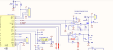
R6 increases the impedance of the DC feedback path, but does not affect the DC gain. Increasing the feedback of the DC feedback allows the AC feedback to have an effect and to work without being shorted out by a low impedance DC feedback path.
C4 is needed to provide a fast AC feedback path, and to stop the circuit oscillating. I can't be sure that the circuit would oscillate without C4 without trying out the circuit, but C4 will certainly slow down the response.
R7 will make sure that the MOSFET is off when the op-amp isn't working at low supply voltages or when disabled with the enable line, which will also happen when the microcontroller is in reset.
R7 is far bigger than R5 so has much less effect than R5. However, when the op-amp is not working, no current can flow through R5. Without R7, that would leave the gate of the MOSFET floating and that could lead to it turning on randomly. R7 will keep the MOSFET turned off until the op-amp is enabled.
D1 doesn't seem to do much. It is common to have a diode in parallel with a coil, to stop the back EMF as the coil is deenergised. However D1 isn't in the right place for that.
D1 may protect the MOSFET if the 12 V polarity is reversed. However the body diode of the MOSFET will probably mean that D1 is not needed.
I don't think it does. When the current stops in the coil the voltage on the coil will reverse, so the bottom of the coil will become +ve compared to the top of the coil. With the top of the coil at +12 V, the bottom of the coil will be very high positive voltage. A diode that isn't a zenner won't help in D1 position.
I don't think it does. When the current stops in the coil the voltage on the coil will reverse, so the bottom of the coil will become +ve compared to the top of the coil. With the top of the coil at +12 V, the bottom of the coil will be very high positive voltage. A diode that isn't a zenner won't help in D1 position.
Back EMF swings both ways, so it gets the other polarity and still provides dampening. Personally I've never stuck a diode that way round, I don't see any point?, but I can see it provides some degree of protection.
So we seem to be dealing with semantics here.
To me, if there is no DC current through a resistor and it has not effect on DC gain than by definition, it's not a DC feedback resistor.
Its sole purpose is to affect that AC feedback.
So we seem to be dealing with semantics here.
To me, if there is no DC current through a resistor and it has not effect on DC gain than by definition, it's not a DC feedback resistor.
Its sole purpose is to affect that AC feedback.
Yes, that was what I mean when I said that it increases the impedance of the DC feedback.
I should have made it clearer that the resistor isn't changing the amount of DC feedback. The resistor is there to allow the capacitor to have an effect on the op-amp input voltage.
This site uses cookies to help personalise content, tailor your experience and to keep you logged in if you register.
By continuing to use this site, you are consenting to our use of cookies.