Continue to Site

Welcome to our site!

Electro Tech is an online community (with over 170,000 members) who enjoy talking about and building electronic circuits, projects and gadgets. To participate you need to register. Registration is free. Click here to register now.

  • Welcome to our site! Electro Tech is an online community (with over 170,000 members) who enjoy talking about and building electronic circuits, projects and gadgets. To participate you need to register. Registration is free. Click here to register now.

Repair a KRK 10s Subwoofer - parts id

Status
Not open for further replies.
No need for the removal of that or other white 5 Watt 22 Ohm resistor, they are quite tough on survival. I was just curious about that smaller resistor under that glue next to that White 5 Watt. The lead sticking out from under the glue shows no corrosion. As for removal of that glue, it's not easy to remove. No solvents that I know of will remove it without eating at the components themselves resulting in damage. The main areas that are typically affected by the glue are high voltage areas like the voltage at the 3206 transistor. Just on the boards where the glue is blobbed, I'm looking at the photos for corrosion at other places where I can see in pnoto around the glue. Over all None of those are corroded. as for the white resistors being loose, those leads are frail by design. Quite flexible hence the glue used, just the wrong kind. Manufacturing use at a lower cost glue. Was meant to hold parts in place against vibration moving the parts loosening and soft leads braking.

I'll just check that the 5 W 22 Ohm resistor is solidly connected.. Kinda seems a bit loose.

Also If I mention anything that is a not sure by all means speak frankly. As I have been quite all over the place, each time I'm looking at the board I wind up seeing something different, or I see a mistake I made and after the post rather than editing it with the slight possibility of it not being seen then causing a back and forth I just add in new info instead, bad habit from me to any one that may not fully understand what I'm in my mind comprehending as I am saying (typing) it.

Completely understand :)

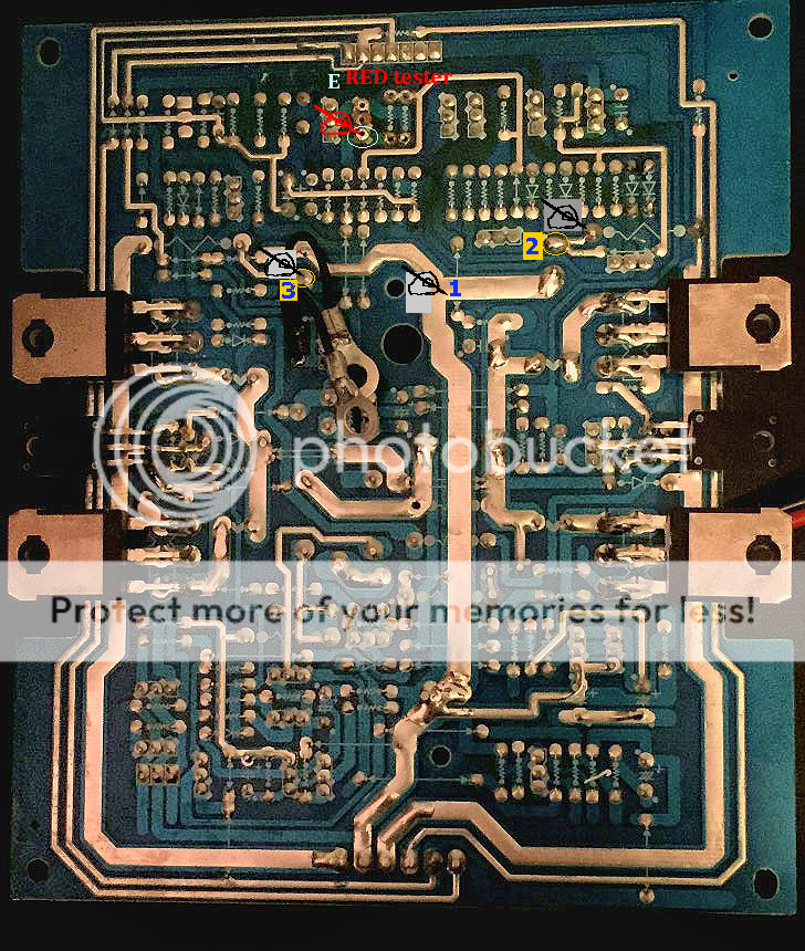
So just to clean up what I think is a possible mess that I have made I'm going to recap with the info gained thus far, Thus far the Transistor that looks very close to a potential replacement is the Panasonic 2SC1473A NPN. only because the leads that I could see on the PCB board for the E from the 3206

(and if I ever call it a 3602 Sorry I am meaning the 3206, I will double check to avoid that. I have at least over 10Gigabytes of transistor and IC components datasheets, you could emagine right?)

No worries GromTag, I'll definitely order the Panasonic 2SC1473A NPN.

continuing, goes to a common ground connection, however I loose the tracks on the backside (solder side) of the PCB near those black wires with ring looms. So "If" the Emitter on that bad 3206 does in fact go to those wire components, then that should be a Ground point as those have to be common connectors, I've not seen what they connect to via the screw used. that aluminum heat sink? of so then those two wires are common Gnd for the sink itself also completing the path to a GND point for the 3206 .

If the track goes else where I cannot be sure with the wires blocking some of the power PCB's view. A photo of that area with those two rings slightly over to the left from the current image all ready posted as a reference to the paths I need to see if in fact the E does go to a common point on the board.

I'm pretty sure it goes to common GND, When I disassembled the pcb from the heatsink, the two small wires that connected to it needed to be cut (because I didn't realize the screw had a hole thru the board (convenience) to un-screw it... Imagine that! What you see in the pics are my re-fabbed ground connector (ring looms).
Either way, I'll trace the board print/solder to see if the 3206 lead to my hackery..

For the P channel I have searched for, looks to be an Toshiba 2SA970 PNP channel, Its collector is driving that 3206 Base on with that Blue acting as a pull down controller to common. In other words when the board switches off that 3206 that resistor is responsible for preventing that transistor from "floating" being on a slight bit resulting in an unstable setting. Small current can reactivate a transistor just like a toggle switch not fully turned on, the contacts on toggles tend to arch. And seeing the voltage on that transistor even with soldered contacts can be no exception due to the voltage. That resistor begins to fail the transistor does not shut down fully/ properly.

As for the Green one, it's a 1K Ohm actually. My first view was of the corroded one, I could only see the brown, black, black stripes. The others over to the left are the same types, Resistor number on the board R481 matches the green as it is seen to be used in many other locations in similar config. The Resistor number R494 to its left from the top (parts) side matches the Blue at 68 Ohms. Both are 1 percent tolerance type resistors. at 1/10 nth wattage size or just 1/10 Watt resistor for internet reference. Decent resistors should be used in those two's places to assure clear operation due to voltage potential slightly heating the resistors changing their resistance values, Colder= slightly higher resistance, lower current flow. Hotter = lower resistance, more current flow.
The Term is PPM parts per million.

A good replacement for Blue 68 Ohm would be RNC50J68R1FSRE6-ND Vishay Dale. for the 25PPM being a bit overkill on current drift but 200Volt max capable. However Digikey is only selling them in droves of minimal orders and have the correct 1/10 size resistors and yet have none in stock... This resistor would be an excellent replacement for the 68 Onm if not for minimum order requirement and stock availability.
https://www.digikey.com/product-detail/en/vishay-dale/RNC50J68R1FSRE6/RNC50J68R1FSRE6-ND/3247484

looking for another shop or a different resistor. Mouser has an 279-LR1F68R 1/8 Watt, that can fit all tho be a bit close on fitting taking all available space for the 1/10 resistors spot. And I'm not fully aware of TE-Connectivity products.
https://www.mouser.com/ProductDetail/TE-Connectivity-Neohm/LR1F68R

A good replacement for Green 1K Ohm (1,000 Ohm) would be from Mouser 279-LR1F1K0 1/8 Watt resistor.
https://www.mouser.com/ProductDetail/TE-Connectivity-Neohm/LR1F1K0
1/8 Watt are typically 3mm in length via the resistor itself. And I often call such small resistors 1/10 out of habit, only using surrounding components to try and gesture their size most of the time.

Thanks!

Certainly seems like the resistors are an easier find even though they're so much smaller than the 3206. I feel lucky that when I walked into Radio Shack
a few weeks ago that they had the diodes I needed when I started this journey. I also feel very fortunate to have you're expert eyes/mind checking this out!
I can follow you when I'm at my computer. I'm glad I'm a software engineer. Q: Do you design your own boards as well?
I've recently become interested in IOT (internet of things) boards. Hashing around a few ideas..I've done some high level
integration on the iOS platform to BTLE devices, but would need to get lower level.
 
Sorry, had a browser update, requiring a restart,
Continuing.

As for the transistor, Still for adequate replacement. Panasonic https://www.digikey.com/product-det...-components/2SC14730RA/2SC14730RACT-ND/972412
That are obsolete but still have stock, however thus far the only I have found close. The 1 concern with this is the resistors are from Mouser, and the Transistor is from Digikey. 2 different shipping.

Will continue to search for those TR-connectivity resistors on Digi. Digi does not appear to have the correct ratings and size, larger resistors can easily be applied to the ports via just bending the wire.
However in some to many audio applications the resistor being lifted above the board be an amount can introduce noise into the components. Depending on how they operate. And as to why I'm trying to prefer a matching resistor type in size to be placed right on the board just like the original ones that were removed.

(and of coarse the decision is and has been yours to make if I've sounded directing in any comments, my bad. I just tend to operate reading like the term "stereo instructions" quite often)

Very good. I can certainly weather the extra shipping costs. Thanks for the sound advice!
I'll also go ahead and inspect the boards up close for any other corrosion (which I hadn't had time to do just yet).
Sorry bout the inconvenient browser update reboot necessity. That's kinda rare on my main computer.
 
Was typing this whilst you were posting the readout info, :) , I'll read that now, this extra can be used to just double check if it's close enough to the test all ready done.

And as for testing the 3206 Emitter terminal to a Common point using those large capacitors.
Multi tool in Ohms mode auto range, Probe common test pin to the large solder track on the center power pcb (from that bottom connector that solder track runs from the bottom of the board in the image and runs up the center of board), then the Red test lead to the E port where the 3206 was located, it would be (looking from the back of board matching the image posted) the lowest port of the 3 ports at the 3206 on the solder side.

The reading would be for E to the large solder track?

And also the meter value may change during testing, the test results being interested in are the initial result value.

Next, same method in auto range, the red test lead still on the E terminal solder side, now the common test pin to the Large Electrolytic caps opposing the large solder tract that goes left and right from center of board. They are vertical mounted on the board from the image. The right one from the solder sides opposing pin is above that large center track of solders right side of board at the tracks end up at that Y looking solder point just to the left of that printed resistor stamp (this is located on the right hand solder side of the board -\/\/- well it actually looks like a W.

what is that points initial reading?

Next the same for the other Electrolytic, its other contact point needed is (from the image) right in that loop of those two wires below the center solder track. a small track goes left then up to the resistor mark (that W again) on the left side of the board solder side.

What would that value be?

Overall the caps are joined in opposing polarity config by that center track comprised of exposed solder requiring only one test on that and then 2 more test, 1 per other pin on those Electrolytic from the 3206 E terminal as reference over all. And as to those caps they are the Push Pull system to the fets control that drives the sub.
 
As for Prototyping, yes at the PCB proto level only, I have not yet gotten into Etching of any type.
For the Circuits I make, they are typical Transistor based throughout. TTL. As for what they do, response to a reaction, meaning a condition that is met can operate the transistors resulting in a control system of sorts.
Security doors I've designed for my own use as these devices are really a never ending learning curve. and some recent field sensors that detect when a person/object gets close enough triggers an output response. Am still working on the antenna types for the field sensors. Inductance matching is a hassle when adding in environment conditions. Sets up at one place, installs another, does not work like it did before kind of issues typically. so over all Basic transistor function projects. However I do tend to be capable of theorizing how a component could work by observing the path, configuration, and with info on part i could get, how it would might work on a board it's on. As for IOT, Networking control of machinery, that is very close to my thrown together shop alarm.
all tho it is not network based, yet. Possibly a wireless plan not too far off. Xbee pro perhaps would be my starting point as the building is only over 100 yards away from here. And if curious about full automation, the Wolfsburg facility in Germany was viewd by me on a series special a few years back on their fully automated parts retrieval facility. How its made if i recall correctly.
 
hmm the second part BTLE blue tooth low energy, do show promise just at initial looking at the references online.
 
The main reason for the test of that 3206 E and those large electrolytic caps. I'm wandering to a possible tied short through any of those fets are present there.

And yes please to attempt to find out if that 3206 E does lead to a common point on the board. Main looking type if possible. thank you.
 
Was typing this whilst you were posting the readout info, :) , I'll read that now, this extra can be used to just double check if it's close enough to the test all ready done.

And as for testing the 3206 Emitter terminal to a Common point using those large capacitors.
Multi tool in Ohms mode auto range, Probe common test pin to the large solder track on the center power pcb (from that bottom connector that solder track runs from the bottom of the board in the image and runs up the center of board), then the Red test lead to the E port where the 3206 was located, it would be (looking from the back of board matching the image posted) the lowest port of the 3 ports at the 3206 on the solder side.

The reading would be for E to the large solder track?

And also the meter value may change during testing, the test results being interested in are the initial result value.

Next, same method in auto range, the red test lead still on the E terminal solder side, now the common test pin to the Large Electrolytic caps opposing the large solder tract that goes left and right from center of board. They are vertical mounted on the board from the image. The right one from the solder sides opposing pin is above that large center track of solders right side of board at the tracks end up at that Y looking solder point just to the left of that printed resistor stamp (this is located on the right hand solder side of the board -\/\/- well it actually looks like a W.

what is that points initial reading?

Next the same for the other Electrolytic, its other contact point needed is (from the image) right in that loop of those two wires below the center solder track. a small track goes left then up to the resistor mark (that W again) on the left side of the board solder side.

What would that value be?

Overall the caps are joined in opposing polarity config by that center track comprised of exposed solder requiring only one test on that and then 2 more test, 1 per other pin on those Electrolytic from the 3206 E terminal as reference over all. And as to those caps they are the Push Pull system to the fets control that drives the sub.

Question: To get theses questions answered am I'm reinstalling the old parts and testing the board in isolation (not powering up)? Or am I getting the new parts installed then testing (again isolated, and not powering up).

Just want to make sure I follow before I get started :)
 
no need to reinstall the parts, nor any power needed, just the E terminal that the 3206 was connected to is all that is needed with the multi tool on ohm auto range with red pin on the E terminal solder side then the common test lead is doing all the wandering work at the other connections mentioned for those two caps, as for their identification method, refer to the image of the solder side when noting the readings, the Right cap is the right one,and the left is the left when looking at the solder side of the power PCB photo posted on forum. As all the necessary contact points are available on that side of board.
 
no need to reinstall the parts, nor any power needed, just the E terminal that the 3206 was connected to is all that is needed with the multi tool on ohm auto range with red pin on the E terminal solder side then the common test lead is doing all the wandering work at the other connections mentioned for those two caps, as for their identification method, refer to the image of the solder side when noting the readings, the Right cap is the right one,and the left is the left when looking at the solder side of the power PCB photo posted on forum. As all the necessary contact points are available on that side of board.


Very good.... I'll get this done in the morning. Thank you!
 
As for Prototyping, yes at the PCB proto level only, I have not yet gotten into Etching of any type.
For the Circuits I make, they are typical Transistor based throughout. TTL. As for what they do, response to a reaction, meaning a condition that is met can operate the transistors resulting in a control system of sorts.
Security doors I've designed for my own use as these devices are really a never ending learning curve. and some recent field sensors that detect when a person/object gets close enough triggers an output response. Am still working on the antenna types for the field sensors. Inductance matching is a hassle when adding in environment conditions. Sets up at one place, installs another, does not work like it did before kind of issues typically. so over all Basic transistor function projects. However I do tend to be capable of theorizing how a component could work by observing the path, configuration, and with info on part i could get, how it would might work on a board it's on. As for IOT, Networking control of machinery, that is very close to my thrown together shop alarm.
all tho it is not network based, yet. Possibly a wireless plan not too far off. Xbee pro perhaps would be my starting point as the building is only over 100 yards away from here. And if curious about full automation, the Wolfsburg facility in Germany was viewd by me on a series special a few years back on their fully automated parts retrieval facility. How its made if i recall correctly.

Neat! I watch that show with my son quite a bit. I'll try to find that particular episode. The never ending learning curve requires the ability to stay in the weeds for extended periods and great attention to detail. My world on software dev isn't nearly that rough even though there's always new things to learn - thankful balance of sorts..

Thanks!
 
I've looked for that episode, Factory made and How it's made. I only recall it was an fully automated facility from a possible Germany branch that handle parts for the automaker, Volkswagen. even with the loaders under automated control. Like an orchestra of moving machines. It's not the Kassel, that's brand new as of 2015, this dates somewhere back to 2006 -2009 at least. If i can recall that well enough. Ahh found it, it's in Europe
Youtube Europe Volkswagen genuine parts distribution center world wide and the perfect chaos vids


I think the vid at the end has been frozen, possibly due to requirements of permission to show the airline and other not ok any more visuals?
 
Last edited:
just a small rant...o_O The only thing here relevant to your amp is that the Driving transistors are actually BJT type Power Transistors. no need to check them as they should be fine, no need to see the numbers hidden between them and the board either.

This contains some concept on how an amp works, however it is not precise, online references are available if more info that is more to the point available.
there are differences in understanding something (which helps out allot) and seeing something quite obviously wrong. Means that repair is not impossible as the bad

obvious part can hopefully be identified then repaired or replaced and then understanding if something elsewhere does not work when the device does not respond

after repairs, then goes onto an attempt at observation and concepts as to what is a potential issue that can still be causing any problems

I have some explaining to do towards those large transistors at the outer edge of the board, on the power PCB I have notice that the indicators such as, B, C, E, is

mentioned, therefore they are likely to be BJT power transistors and not FETS. However in many amp repair methods and clarification of what may actually be driving

transistor method be it BJT or FET, the most direct term when describing an amplifier problem for some reason FET gets mentioned, the repair shop, if they know what to

think or are capable to realize, is the mind goes straight to a potential driver device on the amp board be it main driver array type or a fast switching controller on board that

ate usually quite important for the amps operation or outright ask what the amps potential age is. The latter of question about the age is not so common based on

shops assuming the questioner may not know the amsp actual age. Over all resulting in the eventual discovery if the part is a BJT or a FET in hopeful cases of proper repairs

across distance rather than in shop direcly (hands on). That board does not show to have FET switching components and the reason for those large white 5 Watt resistors

is to dissipate the current gain required by the BJT during switching to handle the heat buildup during operation. Again I called them FETS, tho they are leaning way more

toward BJT. the difference of the two. BJT amps are harder to tune due to the current drift, temperature of ambiant and parts under operation, parts used, power supply

used, and others aside, switching methods. All tho amps can be produced in BJT and FET with direct controlled driver transistors of either two of the types to drive the

speakers driver stage.

The center two could be the switching array supply rectifiers. 1 should be Kathode, and the other Annode type. kathode, arrows pointing to center pin most commonly

are the positive directors, the Annode Negative arrows pointing away from each other. The speaker is suspended in between the positive and negative field and use

the common as the reference only, positive enters, a magnetic field is produced regarding the polarity of amp design and speaker connection will move the speak cone

one way only, (in or out) the common side is lower volt than at the input lead terminal (not all ways positive, some amps use internal inverting on 2 channel ypes at times

to correct for the driver stage using matching switching driver supply methods, Sony XM and GM amps were of this design but listed the markings at wire terminals,

usually one or the other channel, been a while to remember, to polarity when in fact it was inverted internally at one of the channels, so the + was in reality an - and the

other the - in reality a + ) as for the other polarity on negative, the stored power in the coil, currently positive voltage, is allowed to flow to a much lower voltage than

0V common reference, in doing so create the reaction to move the cone in the opposite direction, Fast. Tipical as to why the positive volt is equal or close to the

negative and vise versa. So the term speaker is floating between the rails. the common 0V is actually the reference for both rails (floating rail), even in an unusual sense

that 0V actually flows to anywhere other than negative unless an inductive source is lifting the rail to positive via power feedback of some kind, that is a bad thing in

any amp when a bad design or malfunction occurs. poor speaker connections can cuse this in less severe ranges of power surge. -This is more a push pull concept than

actual amplifier function in description overall-.

Over all even with any company using the board print out for one thing and installing the other, doubtful here. Those have to be BJT. The point, none really other than

the Emitter test of the 3206 shows very low resistance, something may be off somewhere else, if not then the BJT are not likely to be shorted in certain cases and the

electrolytics are Ok. Some driver stages when abruptly shut out or off can result in damage to the driver stage via holding one of the stages on for a long period resulting in

drainage of the Capacitors for power supply, but only one in most cases, now the other still has power and it could produce a "dump" of power reversed so to speak

into the channel licked open. why? Because the Capacitors are, one producing the positive and the other producing the negative voltage, TBH i can't recall right off

hand without looking it up wich stage suffers this problem. Also many amps of recent years even back to the potential late 90's started placing an component of some

kind to prevent this affect. Even using the driver Op Amp via feed back to primarily prevent this. Resulting in one stage passing the other producing an over heat scenario

and eventually (hopefully) pulling the thermistor heat overload sensor. If equipped with ah thermal management, typically are. A basic but not precise method as to how an amp works.

AC Power enters, passes Inductor array of some type, passes to Diode bridge rectifier array, produces High Volt DC with ripple, Large primary and potential secondary

Caps usually Electrolytic as a storage ans smoothing to produce a more stable DC, then from there spit of to potential regulators to change voltage to lower for

processing components, or goes to a DC storage CAP and gets chopped up via a high frequency transistor in single or an array for more ability in handling the effort

that may be needed, then an inductor such as the Toroid a sealed line inductor via the circle more efficient than a ferrite rod type that leaks flux out its ends, (insert a

pun there) DC via transfer via how a transformer woks on a site that has that info for more detail on the transformer if desired on that part, then produces multiple

voltage ranges, such as low for processing parts that get rectified to produce DC again then smoothed more than initial methods, then the high power leads stay

oscillating that move into diode bridge array transistors for the sake of being heat sink mountable due to the heat as they are handling a higher frequency of power and more

than usual current when the system is driven loud just like the switching transistors that drive the speaker, then from there a tie in of low power supply and high

power, where am I at reference for the driving array such as power OP Amps then to frequency control adjacent to signal input methods are close to this point, then to

the driving transistors that switch the speakers again mentioning the main driver array transistors, that in this case are dual pair, two push and two pull, more power avail in a smaller

foot print on the board, and less drive into operation requirement making the entire upstream driving system require less power and with the problems that follow with high power controll. And some more going on elsewhere, such as power monitoring and temperature status controls. this covers about I'd say 10% of whats actually

going on in these by how many amps are produced using different methods to date that I'll never even know of more than likely.
 
Last edited:
enhanced 7 back of POWER PCB test point.png
Trying an image here. about the test points with the 3 multi tool results to test.


Hmm/:meh: no good. workin on it. either pending, or wrong method used, photobucket, i think may be the end of interest.


last try for now, element type link attempt. PNG format

Test result of value:
1

2

3

please and thank you.

enhanced%207%20back%20of%20POWER%20PCB%20test%20point_zps2wyzozzf.png

enhanced%207%20back%20of%20POWER%20PCB%20test%20point_zps2wyzozzf.png

enhanced%207%20back%20of%20POWER%20PCB%20test%20point_zps2wyzozzf.png

enhanced%207%20back%20of%20POWER%20PCB%20test%20point_zps2wyzozzf.png
 
Last edited by a moderator:
Here's goes...

Test result of value:
1 - No reading
2 - No reading
3 - No reading

Given these, I thought I'd test the Meter and I added another spot #4 (the Blue resistor pin) that was just to see if I'm getting any flow, and I did get a reading = a value of 00.2:

Reading.jpg

Also here's another set of pics that may validate I was touching the right 1,2,3 spots, as well as some others that my help you see the
board print, etc.

One.png


Two.png


Without notations:

SolderSide1.jpg

SolderSide2.jpg


Hope this was the expected results :)...
 
Good reading through the 3 points. the 4th reading would read low because the test pins were shorted together. Now on the thin yellow line edited in should be the path from that 3206 E pin and down to those two wires, no matter the enhancement of the photo here, they all need light when photographing to see the tracks clearly. in the image I've posted the yellow again is the track and the green color line edited into photo is a possible track flow to that transistor (Q705) as indicated on a previous image from the topside of power pcb as a reference. The transistor leads in question are the Q705. Just does the the bad 3206 E lead go to the connector of that particular transistor at all? or simply go around it like the yellow line edited in and not have any interaction with it via a board trace in that immediate area indicated by that does track go here in yellow. I will post an image totally unrelated in a bit for an example only.
 

Attachments

  • Test points clear.jpg
    Test points clear.jpg
    543.2 KB · Views: 233
:Not related:
Just using a 3 way touch tone lamp in this example. and downsize did blur the image just a tad as the original was just over 2Mb is size to 838Kb avg in this case. not to clear on the resistor values, however the tracks are visible.
 

Attachments

  • Downsized.jpg
    Downsized.jpg
    302.1 KB · Views: 220
Good reading through the 3 points. the 4th reading would read low because the test pins were shorted together. Now on the thin yellow line edited in should be the path from that 3206 E pin and down to those two wires, no matter the enhancement of the photo here, they all need light when photographing to see the tracks clearly. in the image I've posted the yellow again is the track and the green color line edited into photo is a possible track flow to that transistor (Q705) as indicated on a previous image from the topside of power pcb as a reference. The transistor leads in question are the Q705. Just does the the bad 3206 E lead go to the connector of that particular transistor at all? or simply go around it like the yellow line edited in and not have any interaction with it via a board trace in that immediate area indicated by that does track go here in yellow. I will post an image totally unrelated in a bit for an example only.

I'll see if that track goes down to that spot. Time to get the room lit up and my squinting in order.. Stand by..
 
Good reading through the 3 points. the 4th reading would read low because the test pins were shorted together. Now on the thin yellow line edited in should be the path from that 3206 E pin and down to those two wires, no matter the enhancement of the photo here, they all need light when photographing to see the tracks clearly. in the image I've posted the yellow again is the track and the green color line edited into photo is a possible track flow to that transistor (Q705) as indicated on a previous image from the topside of power pcb as a reference. The transistor leads in question are the Q705. Just does the the bad 3206 E lead go to the connector of that particular transistor at all? or simply go around it like the yellow line edited in and not have any interaction with it via a board trace in that immediate area indicated by that does track go here in yellow. I will post an image totally unrelated in a bit for an example only.

This time I didn't down size it.. It's the lighting and flash effect that make it harder for me.
How does this look? (Personally, I couldn't tell where it's tracking because of the over connecting components).
Some of that metal tracking material looks like it came off from the 3206 E & C pole positions.

Close.jpg
 
Status
Not open for further replies.

Latest threads

Back
Top