Continue to Site

Welcome to our site!

Electro Tech is an online community (with over 170,000 members) who enjoy talking about and building electronic circuits, projects and gadgets. To participate you need to register. Registration is free. Click here to register now.

  • Welcome to our site! Electro Tech is an online community (with over 170,000 members) who enjoy talking about and building electronic circuits, projects and gadgets. To participate you need to register. Registration is free. Click here to register now.

Quick question on 16F628A

Status
Not open for further replies.
Update!

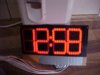
YES! It works now and showing 1202 as I type!

Thanks Eric and all you guys who helped.

Gratefully Al

hi Al,
Show a photo when ready
What did you find wrong?

The Configuration Register doesnt need changing, still called by some Fuses, when they were actual fuses that had to blown to set the configuration.
 
Last edited:
Update on the update.

I have a faulty PIC16F628A! Pin RB5 does not work, I thought it would be my wiring when the F segment did not light but I checked and then finally burnt another 628 and it is now completely ok. I also burnt the original one again, but it still fails.

Never heard of a PIC fault like that before!

Al

Al,
You may recall I had a like problem with a 628A, on PORTA 0,1 pins on that project, would not program as outputs.????
 
Hi Guys,

Not quite ready for congratulations yet Sarma, got minutes upside down, but tens ok. puzzled! more wire swapping on the cards. hehe

Al
FYI Al,
the tens are upside down to enable the use of the dot on displays 2&3 as a colon : (or between dual 7-segs 1&2) to separate hrs and mins.

Getting close now, we await your pics (images ;-) )

EDIT:
Disregard the above...should have read more thoroughly!
 
Last edited:
Hi Guys,

Well I was close then things took a turn for the worse. I did a little rewiring and made the whole display wrong.

Then I thought right, I must not be taking into account the reverse to the rear of the board. So I again rewired and all was strange again. Now I am beginning to wonder if ONLY the 3rd digit across is inverted? I thought that the last two (minutes AND tens) were upside down in the drawing, well I assumed that anyway!

What is happening to my wiring? Can someone tell me is JUST the tens of minutes inverted? Or is it like I thought at first?

Baffled again........Al
 
From my understanding of Jose's schematic, and your own observations, both the minutes and tens of minutes displays are inverted - refer to his 2nd image down, here:
http://www.josepino.com/?led_clock
...and note the position of the dots.

Perhaps I may have to breadboard this to see where things are not going to plan for you. It works OK in Oshonsoft, albeit the minutes & tens of are upside down.
 
Hi Mickster,

Maybe the problem is that in the simulator it is easier to wire up the displays, there is no turning them upside down or wiring them from the rear.

I don't seem to be able to get what few brain cells I have left around the reverse wiring concept, even though I once made another of Jose's clocks and that was charlieplexed and worked ok!

Al
 
while you handle a small and module display easily, physical reversal takes little more time . Take care of all changes.
In your case, you have to wire all segment of units and tens of minutes manually, carefully. Yes lateral inversion issues(looking from behind etc might dog you.
 
Last edited:
Hi Guys,
What is happening to my wiring? Can someone tell me is JUST the tens of minutes inverted? Or is it like I thought at first?

Baffled again........Al

Al,
BOTH minutes are upside down, I still have the BB clock working alongside me.!
E
 
Hi Guys,

Right! Today I am starting afresh with a different method of wiring, I'm going to turn the whole thing upside down to do the minutes ;)

Its just the upside down AND doing it from the rear (sounds like a porn film) that gets confusing!

Anyway once more unto the breech, cross your fingers for me eh.

Al
 
instead of re work, better have a coffee and wire only 8 wires for each digit. Every time you can glow the segment see what it is as seen from top
attach a sticker to the wire concerned later you can handwire easily.
dont increase worklosd
your displays looked otherwise fine.
 
Last edited:
Hi Al (and gang),

I realize you're pretty heavily committed to this design but I wanted to mention that there's a really nice IC out there that might make your next big digit clock project a little easier. It's the Micrel MIC5891 eight bit serial-to-parallel sourcing (high-side) driver. It's a bit expensive though ($2.50 at Digi-key) if you're unable to sample it from Micrel.

k8lh-4-digit-hi-side-png.58930


While there are tons of serial-to-parallel sinking drivers, the '5891 is the only serial-to-parallel sourcing driver I've come across. Anyway, the really nice thing about this IC is that it has a VCC pin for 5 volts and a VBB pin for the LED source (up to about 35 volts). This makes it perfect for those large multi-LED segments on large 7-segment displays.

While I could probably write a Clock program for the MIC5891 hardware in about a day, I'm afraid I don't have time right now.

Happy Holidays everyone.

Cheerful regards, Mike
 

Attachments

  • K8LH 4-digit hi-side.png
    K8LH 4-digit hi-side.png
    13.4 KB · Views: 310
Hi to all,

Thanks again guys for all the help, I couldn't have done it without your support.

Anyway after another go at the wiring of the digits, and a much needed hand from my wife Dawn, who eventually saw where I was going wrong, I have a working clock!

The only small problem I have now is a small one and easily fixed. The 14pin socket I used for the 40106 buffer was an unused but old one, looked fine but the IC seems a bit easy to fit into it and if I tap the board it jumps out! hehehe (hot glue will solve)

Anyway I am posting some pictures of the finished product and should anyone else want to build one I will of course pass on all the help I can. I have a VeroDes drawing of the clock if anyone wants it (you need VeroDes installed but its FREE!) and lets you place components onto virtual Vero Board.

Thanks again guys for the help.

Yours gratefully Al ( at 1:23 precisely)

Edit. The ICs on the left are (top left) PIC16F628A (bottom left)2083 (top right) HEF40106) and (bottom right) under the sheaf of wires is the other 2083
 

Attachments

  • MVC-493F.JPG
    MVC-493F.JPG
    59.2 KB · Views: 173
  • MVC-496F.JPG
    MVC-496F.JPG
    109.4 KB · Views: 167
  • MVC-499F.JPG
    MVC-499F.JPG
    88.5 KB · Views: 176
Last edited:
Nice photo. perhaps she deserves a nice party for helping you finish the product/project.

Just have a feeling that inter digit , there could be little more gap. i saw that the board is limited
then we could use two pcbs , one for hours and another for min.

now with this PCB, you need to place a dark spacer between the inter-digit gap and then pack it in the box. It helps the digits not to be hazy.

IC jumping off the socket___there were similar jokes on ICs falling from Apple or earlier computers. they used to socket all chips and dispatch the computer. when received, the end customer finds all chaps out of those sockets and dancing around, inside the packet.

let us use cheaper I C bases ( not the turned pin type) and they work comfortably.

now coming to your helping others with vero board, perhaps it is better that we make a single sided pcb artwork so that they can not but make a correct clock.
 
Last edited:
Hi Sarma,

Thanks mate, I will be rewarding the wife with an order from our favourite take away tomorrow night!

As for the gaps, it was the only large vero board I had, so I made them to fit as you guessed. I would have liked bigger gaps but until I get some more board it will have to do. I am planning on covering the whole thing in red perspex so it should look a bit better.

The socket I used must be an old Apple one then! heheh Its not turned pin but really sloppy!

Anyway at least everything works ok now and I can move on to the next project that I can mess up.

Al

PS good idea about the black strips between the digits, I will implement that! Al
 
Last edited:
Hi Mike,

That chip does look good, if you do get around to making the circuit and code I would definately make another clock.

Doing this one has made me want a bigger one, I'm thinking of a really big styrene design I have seen on a site once. I think it had 4 inch long segments that were diffused and ran on superbright blue LEDs. It would be great for my mates car repair shop which is a pretty big building.

Anyway off now to make some more magic smoke appear from some unsuspecting IC.........Al
 
Status
Not open for further replies.

Latest threads

Back
Top