Dr.EM
New Member
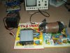
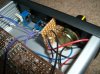
This is a PWM controller design that I have built and which works. As shown, it should function that an increasing voltage applied to the comparator gives an increasing duty cycle at the output, this is variable fully from 0-100%. Swap the inputs on the comparator to give negative correlation if this is desired.
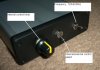
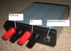
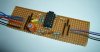
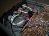
The design uses op-amps to generate a triangle wave which can run at either 120hz or 3khz, this is fed into a comparator input and the reference voltage sets the pulse width. The output of this goes to what is essentially a discrete NOT gate, which is used as the driver for the power MOSFET. I have included control by either a simple control knob, or by an external voltage source. The power MOSFET is heatsinked to the casing which is extruded aluminium (which should make the case live, but when I checked that, it didn't seem to be, mabye the coating is insulating). Tests show it to work quite well, I had to add protection diodes very quickly, even for use with a coiled heater, but thats sorted now. Its all pretty small in its 103x120x30mm case, and should be good for around 10A, tested to 6A with no problems, didn't even get warm.
The design uses op-amps to generate a triangle wave which can run at either 120hz or 3khz, this is fed into a comparator input and the reference voltage sets the pulse width. The output of this goes to what is essentially a discrete NOT gate, which is used as the driver for the power MOSFET. I have included control by either a simple control knob, or by an external voltage source. The power MOSFET is heatsinked to the casing which is extruded aluminium (which should make the case live, but when I checked that, it didn't seem to be, mabye the coating is insulating). Tests show it to work quite well, I had to add protection diodes very quickly, even for use with a coiled heater, but thats sorted now. Its all pretty small in its 103x120x30mm case, and should be good for around 10A, tested to 6A with no problems, didn't even get warm.
Attachments
Last edited:
")