Electro Tech is an online community (with over 170,000 members) who enjoy talking about and building electronic circuits, projects and gadgets. To participate you need to register. Registration is free. Click here to register now.
Welcome to our site! Electro Tech is an online community (with over 170,000 members) who enjoy talking about and building electronic circuits, projects and gadgets. To participate you need to register. Registration is free. Click here to register now.
The hackaweek transistor circuit is a PREAMP, not a power amp. It cannot drive a speaker. It can drive the 33 thousand ohms input resistance of a power amplifier.
The transistor is not biased correctly so it produces extreme distortion.
Why are you stuck on using that horrible class-A heater instead of using a class-AB audio amplifier?
Its input impedance is extremely low, maybe only 7 ohms so the hackaweek preamp cannot drive it.
The hackaweek preamp is no good for a guitar preamp anyway.
I showed you the circuit of a preamp for a guitar pickup that has a very high input impedance because it uses a Jfet, not an ordinary transistor. The guitar preamp can drive an amplifier with an input impedance of 51 thousand ohms.
I'll tell you now, if Mozart had had access to electric guitars, all the effects, amps and digital recording etc he would not have wasted another minute plunking away on that silly piano!
The reason all your beloved classical music is full of pianos and violins etc is because the great composers of the day simply did not have any better instruments! The great composers of today DO.
don't know about that, a guy i used to work with listened to a heavy metal band that used violins, cellos, etc and it sounded just as crunchy as a guitar with the amps that go to 11
don't know about that, a guy i used to work with listened to a heavy metal band that used violins, cellos, etc and it sounded just as crunchy as a guitar with the amps that go to 11
maybe he's just frantically building and testing to make his deadline....
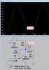
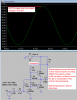
so i played with the first amp circuit i posted and did some of the "tweaking" to see if it would work off +/- 4,5V. the reason i did that is it does take some radical tweaking to get the constant current sources to properly bias the diff amp and voltage amp stage. i purposely did not add the bias diodes for the output transistors because i wanted to illustrate something for the OP. this circuit operates pretty much like an op amp you get in a chip, but it's capable of several watts instead of a few milliwatts. the crossover notch is barely visible in the output waveform, because like an op amp will do whatever it takes for the inverting (base of Q2) input to be equal to the noninverting input (base of Q1). you can see what action takes place to make this happen. there are spikes in the current through Q7 to make Q7 slew through the crossover region, with the result being most of the crossover notch distortion is removed. you can also see this in the near vertical transitions in the voltage at the bases of Q5 and Q6. the crossover notch distortion could be completely removed by adding bias diodes between the bases of Q5 and Q6, but because of the feedback action, you can see that the actual distortion at the zero crossing is very small. i didn't want to do the OP's work for him, but i figured he could learn something about how amplifiers work, that most people have a hard time understanding.
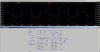
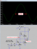
so the first picture shows the tweaked amp and in green, the output waveform, in blue, the emitter current through Q7. and in red the base voltage of Q5 and Q6. the second picture shows a closeup of the same 3 waveforms and the action of the feedback to minimize the crossover notch distortion.
Bit overly complicated for the OP though no need for the current sources - how about replacing them with one resistor, and two resistors with a bootstrap gap for a simpler design?, and run the sim again?.
Following on with the 'simpler' theme, drop the long tailed pair as well, and use a simple PNP at the front end (NFB to emitter).
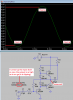
Here is a VERY SIMPLE class-AB power amplifier that is powered from an ordinary 9V battery.
It produces 0.8W into an 8 ohm speaker with fairly low distortion.
Its little output transistors will probably survive playing anything for a long time.
maybe he's just frantically building and testing to make his deadline....
so i played with the first amp circuit i posted and did some of the "tweaking" to see if it would work off +/- 4,5V. the reason i did that is it does take some radical tweaking to get the constant current sources to properly bias the diff amp and voltage amp stage. i purposely did not add the bias diodes for the output transistors because i wanted to illustrate something for the OP. this circuit operates pretty much like an op amp you get in a chip, but it's capable of several watts instead of a few milliwatts. the crossover notch is barely visible in the output waveform, because like an op amp will do whatever it takes for the inverting (base of Q2) input to be equal to the noninverting input (base of Q1). you can see what action takes place to make this happen. there are spikes in the current through Q7 to make Q7 slew through the crossover region, with the result being most of the crossover notch distortion is removed. you can also see this in the near vertical transitions in the voltage at the bases of Q5 and Q6. the crossover notch distortion could be completely removed by adding bias diodes between the bases of Q5 and Q6, but because of the feedback action, you can see that the actual distortion at the zero crossing is very small. i didn't want to do the OP's work for him, but i figured he could learn something about how amplifiers work, that most people have a hard time understanding.
so the first picture shows the tweaked amp and in green, the output waveform, in blue, the emitter current through Q7. and in red the base voltage of Q5 and Q6. the second picture shows a closeup of the same 3 waveforms and the action of the feedback to minimize the crossover notch distortion.
im constantly amazed by how easy for you to design something like that, but how did you arrived with the values of resistors? cause that is my main problem with my design, i have to defend it and explain why i used that or those particular resistors. please help. thanks
Here is a VERY SIMPLE class-AB power amplifier that is powered from an ordinary 9V battery.
It produces 0.8W into an 8 ohm speaker with fairly low distortion.
Its little output transistors will probably survive playing anything for a long time.
may i ask a question if you may, where did the 8.5 v came from? did the 1.3 v from "8.5 - 1.3 v = 7.2 v" came from the two diodes? and also how did you arrive at such values of resistor? please teach me how.
also why is the 8 ohm load connected to the supply dc voltage? i thought the speaker does not need a dc supply?
may i ask a question if you may, where did the 8.5 v came from? did the 1.3 v from "8.5 - 1.3 v = 7.2 v" came from the two diodes? and also how did you arrive at such values of resistor? please teach me how.
im constantly amazed by how easy for you to design something like that, but how did you arrived with the values of resistors? cause that is my main problem with my design, i have to defend it and explain why i used that or those particular resistors.
We were TAUGHT about electronics. It looks like you were not taught about electronics.
1) Simple arithmatic calculates the output currents.
2) The datasheets for the transistors gives the minimum, typical and maximum current gain.
3) Ohm's Law then simply calculates the resistor values.
With a 9V supply (or a plus and minus 4.5V supply) the output swing into an 8 ohm speaker will be about 7V p-p which is 3.5V peak.
Then the peak output current is 3.5V/8 ohms= 438mA.
The minimum current gain of a TIP31 power transistor is about 38 at 438mA so its maximum base current is 438/38= 11.5mA.
Then the current sink for the output transistors should supply 11.5mA. But it doesn't because it was designed for 0.7V/100 ohms= 7mA. So the curcuit will work fine with output transistors with typical or better current gain but will not work if the current gain is less.
That is why I always design a circuit to work with ALL current gains of a transistor (especially the minimum current gain), not just typical current gain.
If you make a single circuit then the current gain of your transistors is not known unless you measure them. Their current gain might be low, typical or better.
If you simulate a circuit with typical transistors then their current gain is typical.
Then your circuit might work only with typical or the best transistors. Then it will not work with transistors that have passing but lower gain.
The negative feedback resistors values are also very simple.
One resistor provides base current to the input transistor so Ohm's Law simply calculates its voltage error and its value. THEORY simply calculates the other resistor value for the voltage gain you want.
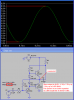
I showed that the maximum undistorted output voltage swing is from 1.3V to 8.5V. I increased the input signal level here to show when the output is clipping with severe distortion then the output signal swing is a little more from 1.1V to 8.6V but you NEVER measure a distorting amplifier.
why is the 8 ohm load connected to the supply dc voltage?
The speaker and the output coupling capacitor C3 BOOTSTRAPS the base current for the NPN output transistor for a higher output signal swing. You need to learn about amplifier bootstrapping (ask your teacher or look in Google).
No.
The diodes have a voltage drop almost the same as the base-emitter voltage drop of the output transistors so the output transistors are always turned on at least a little.
Without the diodes then there is severe crossover distortion because then the input to the output transistors does not turn them on until it is at least plus or minus 0.7V.
Here I show the output when the diodes are removed:
This site uses cookies to help personalise content, tailor your experience and to keep you logged in if you register.
By continuing to use this site, you are consenting to our use of cookies.