Continue to Site

Welcome to our site!

Electro Tech is an online community (with over 170,000 members) who enjoy talking about and building electronic circuits, projects and gadgets. To participate you need to register. Registration is free. Click here to register now.

  • Welcome to our site! Electro Tech is an online community (with over 170,000 members) who enjoy talking about and building electronic circuits, projects and gadgets. To participate you need to register. Registration is free. Click here to register now.

pocket sized guitar amplifier

Status
Not open for further replies.

scripted13

New Member
guys i really need your help !
i have a project on our electronics major, we have to design a pocket sized guitar amplifier. the problem is there are certain things that i do not know
note that we have to calculate all of the components we have to use, we can choose our own transistor but we need a computation on all of the resistors we have to use. can you please help me answer all of the questions clouding up my mind. here are few of those
*what hfe to use or how do i know what hfe should i use?
*what are the maximum and minimum voltage output of a single coil guitar pick up?
*im going to use a 3w 8 ohm speaker, what is the maximum value of voltage input for the speaker?
*how do i solve for the capacitors?
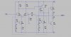
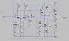
i am using a cascade voltage divider bias on my amplifier design, the voltage gain i need depends on the out put of the guitar pickup and input of the speaker, remember im using a 3w 8 ohm speaker, please help me with my project, this is due in a month so i really have to finish this project and defend it against my professors.

thanks in advance
 

Attachments

  • AMPLIFIER.jpg
    AMPLIFIER.jpg
    278.9 KB · Views: 377
Sorry to be the bearer of bad news - but your 'design' is a complete disaster, it wouldn't be any good as any kind of amplifier. If I was marking the course you'd get a serious FAIL on that, and if it was within my power you're be thrown off the course - I'm presuming you're doing an electronics course?, although that is so bad I can't really believe it?.
 
why? wouldnt it amplify a signal? we are not encourage to use ic because we have to learn the concept of a transistor amplifier, whats so bad about that?
 
I suggest you read up about audio power amplifiers, particularly their output stages. A quick google will also find you the typical pickup output level.
 
I don't know the output of a pickup but I would guess 10mv. The 2n3055 would make a terrible first stage amp. I wouldn't use much more than 12v to a 3 watt speaker. You will need more than 2 transistors to drive the speaker.
 
You do not select the hFE of a transistor. Some are high and others are low. The datasheet shows the range of hFE. Design for the lowest hFE at your maximum current then ANY transistor with that part number will work.

3W in an 8 ohm speaker is (the root of 3 x 8=) 4.9V RMS. The peak-to-peak output voltage is (4.9 x 2.828=) 13.85V.
The output stage will be an NPN-PNP complementary pair of emitter-followers that need a power supply of about 16V or more.
A voltage amplifying transistor or two is needed and the input should be a Jfet with an input resistance of at least 3M ohms.
Negative feedback sets the gain and reduces distortion. A small capacitor is needed to eliminate oscillation at a high frequency due to phase shifts.

The output level from a magnetic guitar pickup is a FEW VOLTS when it is played strongly.

Why didn't your teacher teach you this stuff?

Your circuit is a common-emitter voltage amplifier driving another common-emitter voltage amplifier. Almost no audio power amplifiers are made like that.
 
The extremely simple class-A heater (oops, I mean power amplifier) will probably burn your pocket and burn your skin under the pocket.
Almost nobody uses a class-A room heating amplifier like that (but some weirdos do).
 
I don't know the output of a pickup but I would guess 10mv.
...

Actually most guitar pickups run pretty hot, 1v or 2v p/p is not uncommon when the guitar is played hard.
 
Here is a typical guitar pickup preamp circuit. It has very small voltage gain because the output level of a pickup is pretty high.
It has a high input impedance to allow the pickup's inductance to resonate with the cable's capacitance and produce a "twang" sound.
 

Attachments

  • guitar preamp.PNG
    guitar preamp.PNG
    15.4 KB · Views: 299
  • Guitar pickup peak.PNG
    Guitar pickup peak.PNG
    73.1 KB · Views: 224
Here is your 3W class-A amplifier.
I needed to increase the supply to 24V to get an output of 3W into 8 ohms.
It draws 1.75A from a huge 24V battery.
It dissipates 42W of heat ALL THE TIME even when it is not doing anything.
 

Attachments

  • 3W class-A amplifier.png
    3W class-A amplifier.png
    41.4 KB · Views: 360
i'm not going to give you a complete design, but maybe you can get some ideas here:
https://www.electro-tech-online.com/threads/has-anyone-built-this.473/

basically what you want here is very much like an op amp, but made with transistors, not a chip.

you could use class A, but you a)need to get rid of lots of heat, and b)need to stock up on lots of batteries. class AB or class B (like class AB, but uses less idle current and has fixed bias) will not act as a space heater, needs much less heat sink mass and surface area, uses very low idle current, and doesn't eat lots of batteries. the 2N3055's you had are overkill. TIP31 and TIP32 output transistors (or something very similar) would probably be more than adequate.
 
The extremely simple class-A heater (oops, I mean power amplifier) will probably burn your pocket and burn your skin under the pocket.
Almost nobody uses a class-A room heating amplifier like that (but some weirdos do).

this is just an experimental project, i just need to prove that i can calculate a guitar amplifier, and i need all the computations and explanations on why i use that particular or specific component, i cant just say that i got it from the internet, i need to defend it. im required to use a 9v battery and bjt transistors, please kindly help me with my design, if you have a better configuration than mine then please kindly show me, and also if you know how to compute or calculate the components please show me, also what kind of bjt transistor is best for my project?
 
how about something like this? you will have to change the ratio of R9 and R10 to change the gain of the amp (Av=1+(R9/R10) and figure out on your own what transistors you need. this amp is also "fixed zero bias", so it will have some crossover distortion, you can add a couple of forward biased diodes between the bases of the output transistors to add some bias, and adjust some of the other resistor values to lower the distortion. as i said, i'm not going to do your schoolwork for you, but this schematic is a good starting point. i also recommend you study up on how each part of the amplifier functions, because if i were your teacher, i would certainly be asking you questions about it to see if you know what makes it tick. again, you can look at the article i posted earlier to get the basic idea of what goes on in this amplifier. there's no sense (especially with this being an assignment) in throwing together something somebody else has designed without some clue how it works, and why it's designed the way it is. and i will warn you, this circuit is a rough draft i use for teaching amp theory, the design needs several "tweaks" before it is even a prototype, let alone a finished product. there are a couple of "gotchas" in it (such as the lack of output transistor bias) but that's what makes this an instructional design.


and BTW, you will find that the way this circuit works tends to make individual transistor characteristics not very important, so you don't have to worry about choosing devices with the right Hfe. this circuit will function reasonably well (when you get all of the "gotchas" taken care of) with a wide range of choices for transistors.
 

Attachments

  • simple-amp.jpg
    simple-amp.jpg
    46 KB · Views: 409
Last edited:
im required to use a 9v battery and bjt transistors
Then the output power will be very low and little transistors can be used.
When the little 9V alkaline battery is brand new the maximum output voltage swing into an 8 ohm speaker will be about 6V p-p. Then the peak current in the output transistors is 3V/8 ohms= 375mA.
6V p-p is 2.1V RMS then the output power is only 0.55W like a cheap clock radio.

You can use 2n4401 NPN and 2N4403 PNP output transistors.

Unclejed's circuit will work very well but its has transistor Q6 connected upside down. It is supposed to be an emitter-follower.
His circuit has a dual polarity supply so it will need biasing at its input and three added coupling capacitors.
Also the battery needs a bypass capacitor.
A high input impedance preamp will be needed as I showed.
 
tnx AG... fixed Q6...... must have been one of those things i drew at 3am..... or zero-dark-thirty....
 

Attachments

  • simple-amp-corrected.jpg
    simple-amp-corrected.jpg
    45 KB · Views: 229
Status
Not open for further replies.

New Articles From Microcontroller Tips

Back
Top