Continue to Site

Welcome to our site!

Electro Tech is an online community (with over 170,000 members) who enjoy talking about and building electronic circuits, projects and gadgets. To participate you need to register. Registration is free. Click here to register now.

  • Welcome to our site! Electro Tech is an online community (with over 170,000 members) who enjoy talking about and building electronic circuits, projects and gadgets. To participate you need to register. Registration is free. Click here to register now.

Need help - unusual project

Status
Not open for further replies.

chasegirl

New Member
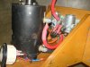
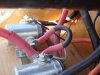
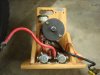
Hi - I build small drag lure machines for dog sporting events and I need help with the wiring diagram for a reversible machine. It needs to be able to go both directions and it has a momentary switch that the operator uses to manually control the speed.

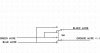
The motor is a 3/4hp heater blower motor. The circuit needs either a relay or a solenoid or both, but I can't figure out how to wire it properly. I've attached my stab at it (wiring3), and the non-reversible diagram that does work for comparison, but I don't think the reversible's right and I need some help.

Thanks in advance...
 

Attachments

  • wiring3.pdf
    234.3 KB · Views: 266
  • wiring_diagram.pdf
    238.4 KB · Views: 224
Hi,

as far as I can see you want to operate a three phase AC motor with a 12V battery.

This is simply impossible.

If you stick to the original wiring diagram (and a DC motor) the motor will be contrallable for both, reverse and rpm-controlled operation. RPM control ist easiest applying PWM.

Boncuk
 
Help with circuit

Hey, thanks for the quick reply! :) But it's not impossible because I don't want to run AC...

I already run a 12vDC motor that way but the motor is not designed for continuous use. It is a winch motor and they burn up if used too much. And they weigh a ton... So, I'm using a single phase 12vDC heater blower motor that is reversible. The manufacturer assures me it's possible but I'm not an electrical engineer - only an inventor. My dad would've known how to do this, but he passed away 3 years ago... :(

The problem with my diagram is that I don't know how to connect the relay with the momentary switch/DPDT switch combo. Do I need a solenoid for each direction or can I just use the relay? I've attached some photos of the big machines we use just for reference. Any ideas would help.

Thanks, again.
 
Okay, I forgot to attach the pictures to my reply... sorry!
 

Attachments

  • injoy1_sept08.jpg
    injoy1_sept08.jpg
    122.7 KB · Views: 227
  • injoy4_sept08.jpg
    injoy4_sept08.jpg
    111.9 KB · Views: 239
  • injoy2_sept08.jpg
    injoy2_sept08.jpg
    117 KB · Views: 238
Where did those brown and green wires come from? They are not in the working schematic. The original schematic shows two wires from the motor. Reversing the motor should be as easy as reversing the leads to the motor with a toggle switch.
 
Last edited:
Hi again,

if you provide specifications of the motor I will design a circuit for you including CW/CCW rotation and speed control for either direction.

The switches (ON/OFF - LH/RH) used may be low power switches. He high current switching will be done using power transistors.

Boncuk
 
Hey, guys -
Okay, the motor in the wiring3 diagram is not the same; I only attached it for reference as to what I've been doing with the drag machines. It is only a CCW rotational motor. The motor I'm using for my field testing is a 7500 rpm, reversible, DC 3-speed motor but I'm only going to use the high speed, hence the brown & green wires. I don't remember what the amperage is but it is a Fasco motor similar to this one: https://www.surpluscenter.com/item.asp?UID=2009021123204232&item=10-1731-B&catname=electric.

I need to be able to run it on high speed, in either direction with a flick of the toggle switch and a momentary switch to actually make it go or release (which is how we control the speed when a dog is chasing the lure on the line that the motor runs).
Hope this makes sense...

Boncuk, are you using a transistor in place of a relay or solenoid?
 
Okay, the motor in the wiring3 diagram is not the same; I only attached it for reference as to what I've been doing with the drag machines. It is only a CCW rotational motor. The motor I'm using for my field testing is a 7500 rpm, reversible, DC 3-speed motor but I'm only going to use the high speed, hence the brown & green wires. I don't remember what the amperage is but it is a Fasco motor similar to this one: https://www.surpluscenter.com/item.asp?UID=2009021123204232&item=10-1731-B&catname=electric.


Okay, I understand better. If you can, it would be a great help to post a diagram like the one in the link you gave, but for your motor; or the part number for your motor if not a diagram. Once the proper connections for your motor are known, for each direction, the switching can be figured out. Motors are different, and the wire colors are not standardized.
 
Last edited:
Sorry about that!

Yes, the motor is a Fasco model 2807510174; it is a 3-speed 5-wire, with the wires being orange for high, red for medium, yellow for low. The label says for CW connect black & brown, power to green; for CCW, connect black & green, power to brown.

The mfgr. tech said to put the orange to the positive side of the battery, brown & green to opposite sides of the switch, black to the negative side of the battery and tape off red & yellow since I'm not using them...
 
I think all you need is a DPDT toggle switch. I don't have anything here at work to draw with, so I can't draw a picture of what i think you need at the moment, but I think its that simple.
 
Hi, Andy - it's not that simple because of the additional momentary switch requirement. The machine needs to go in both directions but the momentary switch moderates the speed and operation. The operator either depresses the switch to make the motor run (in either direction) or releases it and the lure slows down (or stops if you don't press the switch again).

I think the diagram I attached is close but I wanted to get someone more knowledgeable than me to say it either works or doesn't.
 
The momentary switch just turns it on and off, correct? Or do you also need a variable speed drive?

If its just an on and off, it has no bearing on the DPDT toggle. The toggle will select direction and the momentary will make it go.

The momentary switch would either go inline with the ground (-) or orange (+).

The diagram you attached is all we have to go off of. I can't find any info for the motor number you posted.
 
Last edited:
Okay, that's how I've got it - inline with the ground. The next tricky part is adding the relay, along with the fan and power indicator light. I've attached the diagram I have so far. Can you tell me if everything is connected properly?
 

Attachments

  • wiring3.pdf
    244.8 KB · Views: 209
That dosn't look quite right to me.

Whats the fan for? Does that only need to run when the momentary switch is pressed?

Same with the indicator light?

How many amps does the motor draw? The one in the link you provided dosn't look like it draws more then a few amps. I don't see the reason to have the relay in the circuit. Its not going to work the way you have it drawn.

I'll see if I can figure out a way to draw somthing up and post it in a bit, unless someone beats me to it. I hate drawing with MS Paint....
 
Sorry about that!

Yes, the motor is a Fasco model 2807510174; it is a 3-speed 5-wire, with the wires being orange for high, red for medium, yellow for low. The label says for CW connect black & brown, power to green; for CCW, connect black & green, power to brown.

The mfgr. tech said to put the orange to the positive side of the battery, brown & green to opposite sides of the switch, black to the negative side of the battery and tape off red & yellow since I'm not using them...

The manuf tech's info and the label on the motor are not in agreement. Based on the label it's a six wire motor (Orange, Red, Yellow, Black, Brown, and Green) and the connections for CW and CCW are different from what the manufacturer told you. I see no info on the internet. How many wires are connected to the motor, again (five or six)? The two speed motor has five wires, so it makes sense that your three speed motor has six wires. Should we go with the label info?
 
Based on the drawing in the link you posted, here is how I think the switch should be wired.
Let some others look at it before you rush and change anything, I have been wrong before. lol :D

Note that Blue and Green don't get connected, they just cross over eachother in the drawing.
 

Attachments

  • switch.jpg
    switch.jpg
    11.8 KB · Views: 194
Last edited:
Okay, guys... there are 6 wires on this motor; it is NOS and no longer made by Fasco, which is why you couldn't find anything on it. You're right - the colors are my mistake. That should be black and brown on either side of the switch and power (-) to green. I'll switch that - thanks!

Now, about the fan & light. They go on when the master power switch goes on and stay on whether or not the momentary switch is depressed. The relay is in there because the momentary switch tends to fry when depressed even with these small motors. I installed the switch in my smaller machines (1/2hp CCW 12vDC) and it solved the problem. This machine has to have the same features as the little machine, so the fan, the light, the master power switch, are all kind of necessary... have either of you been to my website? If you go to the machines page you can see what the application is, which may or may not help. Go to Wicked Coursing Home Portable Lure Coursing Machines
 

Attachments

  • wiring_diagram.pdf
    238.4 KB · Views: 232
Holy smokes - National Lampoon, April 1976: "Dog fishing in America".
 
Yes, I did look at your website, so I have an idea what this is for, but it dosn't help me in assisting you with the wiring.

The picture I was working off of has 5 wires.

Your motor has 6 wires.

What is the 6th wire for? Is the 5 wire picture even relevant?

You mentioned earlier its a 3 speed fan motor. The 5 wire picture is a 2 speed motor. Is the 6th wire an addtional speed?

If you can give me a clear idea of exactly what wires need to go where for CW and CCW rotation, I think I can draw you a schematic. But I can't really follow you descriptions.

I take it this is somthing you are going to mass produce, atleast on a small scale? Why not use a motor that is still manufactured?
 
Last edited:
Hmm... the motor I'm trying to use is a 3 speed but I only need one speed - high. The reason I'm using this is because I can't find a single speed, 7500rpm 12v DC blower motor with enough torque to run a 500 yard line with a 7" pulley. This motor is just a tester to see what it does - draw, torque, overheating, etc. The mfgr. will build a motor to my specs once I figure out what I need but I can't do that til I do some field tests. The other motors out there in production are usually too big and too slow. So. The "wiring3" diagram is as close as I've been able to get. It has 4 wires and assumes the other two (red - medium; yellow - low) are taped off.

According to the mfgr., orange goes to +, black & brown go to opposite sides of the switch for CW and CCW rotation, and the green goes to ground. I've drawn in the master power and momentary switches how I thought they'd go. The relay, fan & power indicator light are drawn similar to the the other schematic I attached (wiring_diagram), so that one is just for reference.

The picture of the 5-wire, 2-speed motor was also just for reference and ballpark specs. Didn't mean to confuse the issue. :eek:
 
Status
Not open for further replies.

Latest threads

New Articles From Microcontroller Tips

Back
Top