Smartsword
New Member
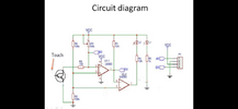
Metal detector:
I have an urgent question!!
Like the video in the link:
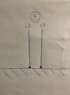
The copper wire has two connections...But only PIN2 is shown in the video?!?
How i connect the two end of the wire?

I have an urgent question!!
Like the video in the link:
The copper wire has two connections...But only PIN2 is shown in the video?!?
How i connect the two end of the wire?