Continue to Site

Welcome to our site!

Electro Tech is an online community (with over 170,000 members) who enjoy talking about and building electronic circuits, projects and gadgets. To participate you need to register. Registration is free. Click here to register now.

  • Welcome to our site! Electro Tech is an online community (with over 170,000 members) who enjoy talking about and building electronic circuits, projects and gadgets. To participate you need to register. Registration is free. Click here to register now.

SMPTE IC to OLED Display

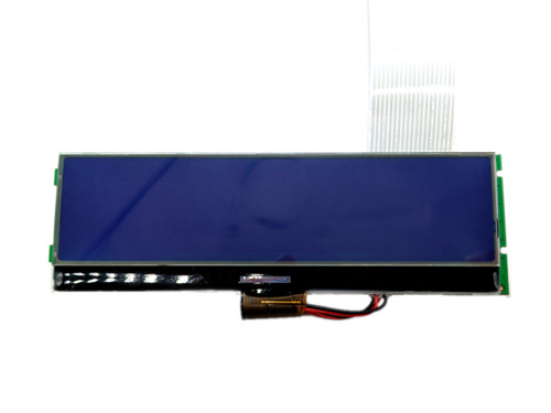
I'm in the process of that IC SMPTE that is already in an instrument. I would like to convert the signals from it to LCD/OLED display. I'm considering an RPI2 microcontroller. But I don't know how to decode the SMPT IC to generate video/audio signals to the path. What I have seen from the schematic is just the video signals ONLY decoded into the current LCD display which I want to use an alternative one. The original LCD is 248x60 How to approach that please? Any suggestions?

1710074495617.png


1710074507420.png
 
Nigel Goodwin It's discontinued, that's why I'm trying to replicate my own.
So my approach would to record the commands from the LCD socket,..etc ?
But don't you see that the LCD is a normal Char LCD ? is there a mystery protocol around it ?
If I want to do it the hard way, can you explain to me the steps ?
 
Nigel Goodwin
Thanks so much for your support.
After a lot of research, I have found a compatible LCD/Driver. Here is the datasheet, what is your view and opinion on that ?
 

Attachments

  • SED1561_v3.0.pdf
    536.4 KB · Views: 44
  • S1D15605_ETC.pdf
    677.1 KB · Views: 45
It's the same display module as various Akai machines.

There are replacement displays for those available.
eg.


From another forum -
I need a new display for my akai mpc2000 part number s-11114b
I also found some pictures of dismantled machines showing the same S-11114B display module.
 
Get a cheap logic analyser such as a Saleae Logic 16 & connect to all the signals to the display.

Capture the data sequence and compare it to the LCD commands for various controllers. It's almost certainly a bitmap pattern plus addressing data.

The single address line usually selects either the display memory (the bitmapped pattern data) or the control register(s).
 
Nigel Goodwin rjenkinsgb
1. What is A1 in the socket responsible for ?
2. The approach is to interrupt on IOWR, read the data and follow the commands in various controller
3. After deciphering the commands, I should collect the data and make a full 2D Frame buffer
4. OR do the same commands, that comes from the CPU to my own LCD, for example the CPU issues a DrawChar, I should also give a command to my own LCD controller to DrawChar ?
5. Write to another LCD that Bitmapped 2D Frame buffer ?
 
Last edited:
A1 is an address line from the CPU - it selects access to the control or data registers in the LCD.
For the display, it's just a two way address select, A0 (lowest order address bit) as far as the display is concerned.

Most present parallel interface graphic displays call it D/C (data / control) instead of address - but its exactly the same thing.

See page 5 of this for a typical interface such as that. It uses A0 from the CPU rather than A1, it's just whichever address line the designer thought suitable - it's still the same D/C function at the display.

Page 4 of that also gives you an idea of the typical commands that can be used - not many, mostly to select the address or range that the next data will be written to or read from.

The internal "address pointer" increments on each data read or write, so you set that then send as much data as appropriate.


An MCU with a parallel slave port could be ideal as a "converter", as that could directly accept data from the existing LCD connector.

However, the LCD interfaces - especially older ones - tend to be relatively slow and any present fast MCU would likely be able to emulate it in software - an STM32, RP2400 or ESP32 etc.

If you arrange the data (to D address) appropriately, it should give a direct bit-to-pixel mapping of the displayed image.
 
rjenkinsgb
Thanks so much really.
can you please give me details on the software approach ? like steps or pseudo code ? this will be the last question
I can't find a fast speed microcontroller with parallel slave port in it.
The ones that I have seen are PICs and they are not fast ?
Also on the PIC parallel slave port, I have seen WR,RD,CS pins, should I connect these to the LCD socket too ?
 
Last edited:
In newer PICs, the peripheral is called PMP, parallel master port - which can also work as a slave port. I'm not sure if it is 8 bit only.

Someone has done a similar thing with an STM32, here - they are saying it was not initially working, but the answer (move the DMA init line) apparently works:


That's using one of these MCUs:
 
The "clock" is the data capture trigger; from the LCD interface it would be the OR combination of the two chip select lines and IOWR (so when all three go low that signal goes low), as that's when the LCD would see a valid data write.

Sorry but I do not have time to go in to the software in any depth, I'm way behind on my own projects!

You need to capture data first, then compare that to the displayed image to figure out the mapping.

(If that SED1561 is compatible, the data to pixel mapping is on page 39 of the datasheet. Just rotate that to landscape view).
 
Last edited:
rjenkinsgb
Thanks so much for your support, I wish you the best for your projects.
Regarding software:
I have a plan like to write a big state machine, once the A0 is a data register, I put the data into a buffer, as they are pixel data, if A0 contains command data, I group the commands, then act on them.
The question is I should wait first for commands, then data right ?
 

Latest threads

New Articles From Microcontroller Tips

Back
Top