Electro Tech is an online community (with over 170,000 members) who enjoy talking about and building electronic circuits, projects and gadgets. To participate you need to register. Registration is free. Click here to register now.
Welcome to our site! Electro Tech is an online community (with over 170,000 members) who enjoy talking about and building electronic circuits, projects and gadgets. To participate you need to register. Registration is free. Click here to register now.
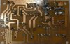
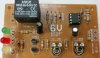
What is **broken link removed**thing and what does it do? I googled "6v low voltage cutoff" and found **broken link removed** somewhat similar looking circuit. Please help me with it. Thank you.
You have the board, so make a schematic of what you do know as to the parts. Looking at pictures of a board isn't anything but a guessing game for us, unless someone has the same identical board they may have seen or worked on in the past. Make a schematic and post it.
A 741 opamp is 44 years old. It was designed to use a 30V supply. Many will not work on a supply that is only 10V or less.
Its inputs must be at least 3V above the negative supply and at least 3V below the positive supply. With a 5mA load its output might have a 5V high and low loss.
You can do it with a transistor, relay and zener diode. Plus a few parts
Here is the version for 12v: **broken link removed**
LOW VOLTAGE CUT-OUT
This circuit will detect when the voltage of a 12v battery reaches a low level. This is to prevent deep-discharge or maybe to prevent a vehicle battery becoming discharged to a point where it will not start a vehicle. This circuit is different to anything previously presented. It has HYSTERESIS. Hysteresis is a feature where the upper and lower detection-points are separated by a gap.
Normally, the circuit will deactivate the relay when the voltage is 10v and when the load is removed. The battery voltage will rise slightly by as little as 50mV and turn the circuit ON again. This is called "Hunting." The off/on timing has been reduced by adding the 100u. But to prevent this totally from occurring, a 10R to 47R is placed in the emitter lead. The circuit will turn off at 10v but will not turn back on until 10.6v when a 33R is in the emitter.
The value of this resistor and the turn-on and turn-off voltages will also depend on the resistance of the relay.
This site uses cookies to help personalise content, tailor your experience and to keep you logged in if you register.
By continuing to use this site, you are consenting to our use of cookies.

")