Continue to Site

Welcome to our site!

Electro Tech is an online community (with over 170,000 members) who enjoy talking about and building electronic circuits, projects and gadgets. To participate you need to register. Registration is free. Click here to register now.

  • Welcome to our site! Electro Tech is an online community (with over 170,000 members) who enjoy talking about and building electronic circuits, projects and gadgets. To participate you need to register. Registration is free. Click here to register now.

Help fixing Panasonic TNPA5808 (SMPS) low voltage issue

madhu1991

New Member
I'm trying to fix an old Panasonic LED TV, mainly for educational purposes.

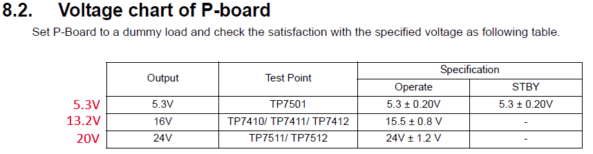
While I was checking voltages on the P-Board I got to know the voltage of the SRV-16V rail is 13.2V (with and without dummy load).

Both 16V and 24V rails are bit lower than specifications. However the 5.3V standby line is good.

image.png


I have tested diodes, transistors and some other parts and didn't find any issue. This seems beyond my knowledge.

Please help me to solve this issue. Thanks
:)


A91ewsq8c-1yhbb0o-few.jpg


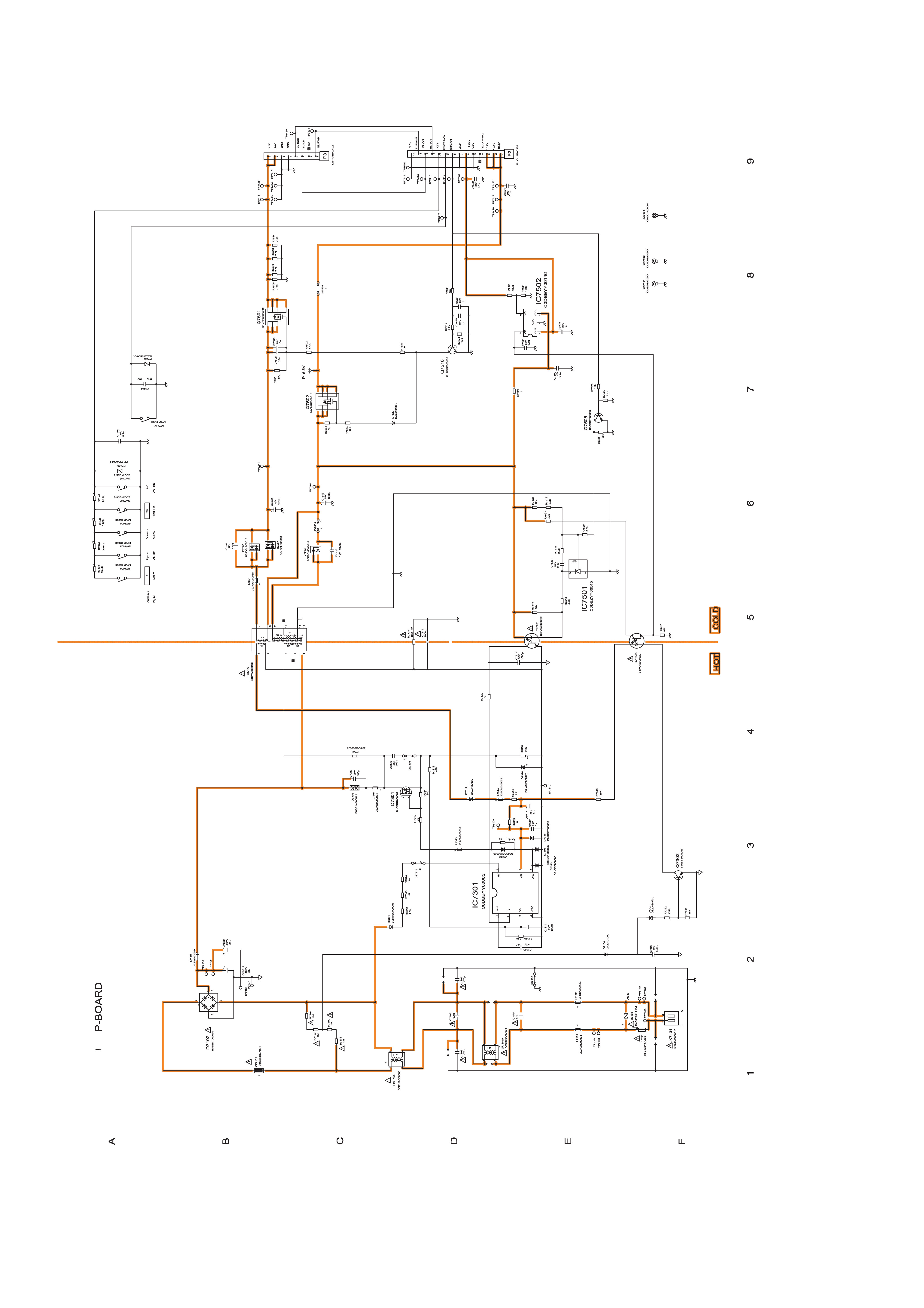
PS: Schematics is attached.
 

Attachments

  • A91ewsq8c_1yhbb0o_few.jpg
    858.3 KB · Views: 41
Without the board connected to the TV the supplies may not read correctly anyway, but the most common issues are high-ESR electrolytic capacitors, such as the reservoir capacitors on the output rails. You can check them unpowered in-circuit with an ESR meter, or with the board powered up using an oscilloscope on the capacitors, if they are high ESR you will get high ripple on them.

So are your readings with the board connected to the TV, or have you connected the board to dummy loads as specified in the list above?.

For that matter, is there any reason you suspect the PSU board is at fault?.
Thanks fro the respond :)

I checked by putting a dummy load and without a load both readings were 13.2V

However with A-Board connected,

Both 16V and 24V within specifications.

16V reads 15.5V and 24V reads 23.2V


This TV was working fine and I didn't use it for long. When I try to turn ON the TV, the green LED is steady ON. Not responding to any button no blinks, no red LED or nothing at all. Only green LED lights up continuously.

I checked voltages on A-Board and all fine. Only PNL12V and 5V to USB connector is missing.

I think MT5307 is not turning them ON.

image.png


These pins should be High to enable those as I learned.
 
Last edited:
Nigel Goodwin

I was looking at a wrong pin. It's not pin 102. They are Mediatek's 104(USB_DN1) and 105 (USB_DP1). It seems USB_DN1 is enabling following circuit

image.png


and USB_DP1 enabling PNL12V. Any thought why the Mediatek is not activating them?
 

Latest threads

New Articles From Microcontroller Tips

Back
Top