StudentSA
Member
Good Day,
I am struggling with what I thought was a simple enough circuit. Would like to know what the correct way would be to handle this situation. I have two voltage rails, 5V supply (V_BUS) and 3v3 (from a LDL1117S33R buck). I am trying to get a LED to turn on when the 5V supply is available i.e. by default when 5V DC supply is plugged in the LED should be on indicating that there is power.
We have a 3v3 microcontroller that I would like to use a gpio to control the power led as well so we can use PWM etc to manage brightness etc.
My initial circuit attempt is as follows:

This works for the most part, however I am noticing some weird behaviour on the microcontroller side which I think is linked to the fact that I am pulling the GPIO (PWR_LED line) to 5V in this circuit which is probably not the best thing to do given it is running off 3v3.
Im guessing I need to run two mosfets one to isolate the 3v3 and one to drive the 5V.
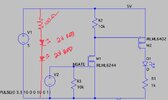
I evaluated the following circuit (in LTSpice) using a P and N channel enhancement mode mosfets. however on simulation I see I have the logic inverted. i.e. LED is off by default and only comes on when 3v3 is applied:

Would really appreciate assistance in correctly designing a circuit where the LED that is ON when no signal is present (floating or 0) from microcontroller GPIO and is controllable i.e able to switch off when GPIO is at 3v3.
Thanks.
I am struggling with what I thought was a simple enough circuit. Would like to know what the correct way would be to handle this situation. I have two voltage rails, 5V supply (V_BUS) and 3v3 (from a LDL1117S33R buck). I am trying to get a LED to turn on when the 5V supply is available i.e. by default when 5V DC supply is plugged in the LED should be on indicating that there is power.
We have a 3v3 microcontroller that I would like to use a gpio to control the power led as well so we can use PWM etc to manage brightness etc.
My initial circuit attempt is as follows:
This works for the most part, however I am noticing some weird behaviour on the microcontroller side which I think is linked to the fact that I am pulling the GPIO (PWR_LED line) to 5V in this circuit which is probably not the best thing to do given it is running off 3v3.
Im guessing I need to run two mosfets one to isolate the 3v3 and one to drive the 5V.
I evaluated the following circuit (in LTSpice) using a P and N channel enhancement mode mosfets. however on simulation I see I have the logic inverted. i.e. LED is off by default and only comes on when 3v3 is applied:
Would really appreciate assistance in correctly designing a circuit where the LED that is ON when no signal is present (floating or 0) from microcontroller GPIO and is controllable i.e able to switch off when GPIO is at 3v3.
Thanks.