Continue to Site

Welcome to our site!

Electro Tech is an online community (with over 170,000 members) who enjoy talking about and building electronic circuits, projects and gadgets. To participate you need to register. Registration is free. Click here to register now.

  • Welcome to our site! Electro Tech is an online community (with over 170,000 members) who enjoy talking about and building electronic circuits, projects and gadgets. To participate you need to register. Registration is free. Click here to register now.

LM3914 with a buzzing relay

dobbsincrete

New Member
I am building a 5v humidity control for my bathroom extractor fan.
The circuit, (image attached), is based on information I have read on the internet and uses an LM3914, an led bar graph, a transistor and a 5v relay. The humidity sensor I have is the Velleman mm102. Seemed like a nice little project, but …..
I am having a problem with the transition between the LM3914 outputs.
As the humidity level changes, and the selected led level comes in to play, the transition, if slow, causes the transistor to not switch cleanly. This then makes the relay buzz briefly and the contacts not operating or releasing cleanly.
Does anyone have a way around this please?
Any help or guidance would be much appreciated.
Thank you
Fan Control.jpeg
 
Thanks Tony & ZZO for your comments and technical suggestions - quite heavy for a diyer like myself - but I can certainly see the importance of understanding data sheets.
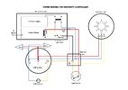
Attached is a diagram of how the controller fits in. It’s also worth noting that the fan does have a run-on timer.
 

Attachments

  • Mains Wiring.jpeg
    Mains Wiring.jpeg
    64.5 KB · Views: 72
I don't know this sensor. Is it relative or absolute?
I see a measurement range: between 11% and 89% humidity.
That looks like split phase 240V extractor (wind tunnel ;)

I wonder how you choose between days of rain and dry winter for the threshold to turnoff.

What will you choose? 88% ON and ?? for OFF ? What if the ambient is high?


In my bathroom, I installed an IR motion sensor to replace the switch to automatically turn light AND fan and it has an optional delay off timer in minutes, where I chose 4 minutes. It also includes a manual switch. (push-push toggle)

ps.

The other thing that just occurred to me was something Nigel & ZipZap were alluding to. If it only has 1 or 2 LEDs that are on at a time, this bar-graph chip may not work well in dot mode, whereas bar mode turns on all LEDs up to the peak one. After you decide on the threshold input voltage for On and Off and want hysteresis . there may be an easy solution or not.

This requires a calculated threshold and hysteresis resistor values relative to the 5V reference and positive feedback.

If you decide a change like this is needed , define your voltage thresholds and we'll help out with a fix.

This IC has a dozen or so precision comparators built in.
 
Last edited:
Hi Tony, the Velleman sensor details, although no longer available, can be found here: https://cdn.velleman.eu/downloads/0/user/usermanual_mm102_en.pdf
As you can see, the output has about a 2v swing.
My plan was to get this up and running on the bench before cutting holes in the bathroom ceiling. At the moment the fan comes on with the light switch and runs on for about 5 mins after the light is turned off. Which is fine until you need the loo in the middle of the night!!
The idea of my little project was that the fan only comes on when showering as I am not particularly interested in the actual %RH numbers.
Using the LM3914 in bar graph mode is very flexible in that it can be visibly calibrated using both the 10k pot on the input pin 5, and also, by means of the selected output led (I am in fact only using 7 led's, pins 11 to 17).
Once set, leave it alone unless it fails, hence the manual changeover switch on the box to go back to the light switch operation - see the mains wiring diagram.
Sorry about the extractor fan symbol, it was all drawn up in Word!!

You might want to consider replacing the BJT with a PMOS mosfet that has a low VGS(th).
Then the base current draw issue goes away. Just requires a gate Pullup resistor (maybe 10k or so) to +V supply.
 
Thanks eTech. Sorry, but never having used mosfets, could you suggest one please. Many thanks
Your problem of relay chatter has nothing to do with current limitations of the transistor. Read the datasheet of the LM3914 - it clearly says transistion from one LED to the next are intentionally slow to show a dim-to-bright transistion. That, coupled with the extremely slow transitions of humidity changes from your analog sensor output.
Option 1: use the recommendation in the datasheet to use the dot-version with hysteresis. Unfortunately, the bar setup cannot work with hysteresis. the dot version means your relay will trigger only when the single pin 10-18 used for your transistor base (or gate) is triggered. You'll need to parallel all higher pins associated with higher voltage inputs to the one you want which defeats your desire to use the LM3914 for its multiple comparitor outputs.
Option 2. Use a real comparitor with hysteresis and add a potentiometer as one input to the comparitor that allows you to set the fan as a humidistat. This is the right way to solve all of your problems instead of using a chip that is an innovative use of an LM3914 but not a typical use and you are running into some of the "features" of the LM3914 that seem like bugs in your application.
 
Many thanks for all of your thoughts and suggestions on my little humidity controller project.
After a lot of playing and modifying I eventually come to the conclusion, as a number of you had previously commented, that my circuit using the LM3914 was not a great idea. Basically, with slowly varying voltages coupled with the LM3914 transitioning between levels, the poor little relay was never sure what to do!!
The solution I now have is to use a LM393 comparator with hysteresis coupled to a MOSFET to operate the 5v relay. This now gives the circuit time to fluctuate slightly with the small voltage changes while at the same time the relay remains unaffected.
The data sheet that was really useful for me was:
Attached is the circuit that I am planning to use, but the bench tests look very promising. Once in situ, I guess, there will be some calibration required as I have no idea what the humidity level will go up to when showering!!
So, thank you all once more - although comments still gratefully received.
 

Attachments

  • DocV2a.jpg
    1.1 MB · Views: 49
Many thanks for all of your thoughts and suggestions on my little humidity controller project.
After a lot of playing and modifying I eventually come to the conclusion, as a number of you had previously commented, that my circuit using the LM3914 was not a great idea. Basically, with slowly varying voltages coupled with the LM3914 transitioning between levels, the poor little relay was never sure what to do!!
The solution I now have is to use a LM393 comparator with hysteresis coupled to a MOSFET to operate the 5v relay. This now gives the circuit time to fluctuate slightly with the small voltage changes while at the same time the relay remains unaffected.
The data sheet that was really useful for me was:
Attached is the circuit that I am planning to use, but the bench tests look very promising. Once in situ, I guess, there will be some calibration required as I have no idea what the humidity level will go up to when showering!!
So, thank you all once more - although comments still gratefully received.
If you can see the steam in the room, the humidity is 100% - it just may take time for the humidity sensor to read 100%, and once it does, it make take some time for any condensed liquid in the housing to dissipate and read below 100%.

Also note that some humidity sensors are designed for 15-85% with questionable accuracy outside of that range.
 
Thank you ZZO, and yes, you're right at 100% RH you can see the steam. At lesser humidity levels, though you cannot see it but you know it's there because condensation appears on the mirror and wall tiles.
According to the user manual, the 5v Velleman MM102 sensor gives an accuracy of +/- 3% between RH levels of 11% - 89% with a response time of 5 seconds.
From the bench tests that I've made, the sensor outputs were:-
Ambient room ~ 2.07v (although yesterday it was 1.99V)
Over a hot cup of tea 4.64v
Warm air from a hair dryer. 1.27v
My breath 4.25v (a lot of puff!!)
I will say that the response time appears to be much faster than the 5secs quoted.
I guess ceiling location of the sensor will be crucial with respect to the extractor intake. Anyway, all good fun!!
 
I think it makes more sense to use an automatic fan & light on with a motion sensor with a programmable turn off delay, found in any big-box hardware store. You just rewire both light and fan loads replaced by this one switch.
 
Thanks for your reply Tony, but the extractor fan is really only needed when showering, not when I need to get up in the night for a pee - an age thing!! The fan already has a six minute delayed turn off.
 
I forget where I read this, but if you turn the light on normal brightness, it’s not as easy to fall asleep again. So if you do get up at night, keep the light low, but bright enough to see.
Maybe motion with lighting level automation is a way to go…
 

Latest threads

New Articles From Microcontroller Tips

Back
Top