Continue to Site

Welcome to our site!

Electro Tech is an online community (with over 170,000 members) who enjoy talking about and building electronic circuits, projects and gadgets. To participate you need to register. Registration is free. Click here to register now.

  • Welcome to our site! Electro Tech is an online community (with over 170,000 members) who enjoy talking about and building electronic circuits, projects and gadgets. To participate you need to register. Registration is free. Click here to register now.

LM3914 with a buzzing relay

dobbsincrete

New Member
I am building a 5v humidity control for my bathroom extractor fan.
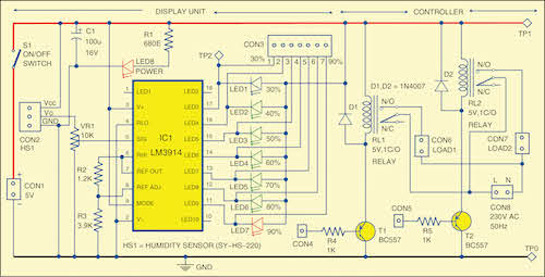
The circuit, (image attached), is based on information I have read on the internet and uses an LM3914, an led bar graph, a transistor and a 5v relay. The humidity sensor I have is the Velleman mm102. Seemed like a nice little project, but …..
I am having a problem with the transition between the LM3914 outputs.
As the humidity level changes, and the selected led level comes in to play, the transition, if slow, causes the transistor to not switch cleanly. This then makes the relay buzz briefly and the contacts not operating or releasing cleanly.
Does anyone have a way around this please?
Any help or guidance would be much appreciated.
Thank you
Fan Control.jpeg
 
The other possibility is to replace the BC557 with a low vgs(th) PMOS MOSFET transistor.
Then you only need a pull-up resistor (10k) with no gate resistor and there would be no significant transistor current draw from the LM3914 output pin..
 
Without that, there is no absolute guarantee that the base feed (a LED output) will be held near enough 5V to avoid some current through the transistor.
The LM3914 turns LEDs on/off (via pins 10-18) with a constant current, current sink from open collector comparitors. That is, when the LM3914 turns an LED off, the cathode side of the LED is essentially floating with less than 10uA leakage (less than 0.1uA typical).

This off-state leakage is really not a concern because, even with the max 10uA leakage and max gain of a BC577 PNP, the circuit will only put 2.5mA through the coil of the relay. 2.5mA Is well below the switching threshold of any relay I'm aware of. Also, the OP has not complained of any relay chatter in the off-state, only in the on-state.

Note, leakage on Pin1 is, of course, much higher and should not be used in this application. About 15x higher.
 
the circuit will only put 2.5mA through the coil of the relay. 2.5mA Is well below the switching threshold of any relay I'm aware of.
... but it's within the hold range of many relays!

The specific 5V one in use is actually rated at 4mA "Must release", but eg. the 12V version must release current is only 1.6mA.

And, you are assuming full spec components, not economy out-of-spec or clone parts.

Not guaranteeing full turn-of on any switching transistor is just plain bad practice.
Are you kidding? A cheap relay with more turns and triggers (or holds) at lower current than a specified. I'm sorry, but cheap relays have higher resistance wires or fewer turns than a "specified" relay - that always run hotter, require more current than a good relay.

And your claim that a 12v relay has a must release current in the low range so, somehow a corresponding 5v relay that has a 4mA must release current means you are right, well, I'm not going to argue with someone grasping at straws just for the sake of making themselves sound like they could be right. Arguments like that never end and never make sense - when we are using a 5v relay. Right?

Because it's NOT in the hold range of ANY 5v relays that can handle the switching current of a bathroom extractor fan.
 
Leaving the base floating on a transistor in the off state is, categorically, bad practice.
Of course that's a bad idea, in general, but my actual numbers from actual datasheets of multiple worst-case part specifications show it's not going to cause chatter of an actual 5v relay if the available on-state current is below the worst case "must turn off" current of said relay.

In other words, it's good practice but, the OP should most likely look to other options to solve his problem.
 
Thank you Nigel for your reply.
Just for info, the relay that I am using is a Finder 32.21.7.005.2000 5v relay with contacts able to switch up to 6 amps.
I agree, and am beginning to wonder if my choice of control circuit was in fact a good one. It would seem that the output voltage from the humidity sensor fluctuates slowly which is then reflected in the output from the LM3914 and then on to the BC557 and ultimately the relay. It looks like in isolation each component is doing its bit correctly but overall not necessarily correctly.
Anyway, I'll see how rjenkins mod goes for now.
FYI the original circuit for my project came from:
Thanks again to you all for you interest and suggestions.
 
I agree, and am beginning to wonder if my choice of control circuit was in fact a good one. It would seem that the output voltage from the humidity sensor fluctuates slowly which is then reflected in the output from the LM3914 and then on to the BC557 and ultimately the relay. It looks like in isolation each component is doing its bit correctly but overall not necessarily correctly.

Sorry, but it was an utterly bizarre choice, completely the wrong component, and one that's long obsolete and difficult to source. As someone mentioned back near the start of the thread you just want a simple (and cheap) comparator chip, and apply positive feedback to give hysteresis.

The LM3914 is full of comparators, but you don't have direct access to them, and they are 'obstructed' by other components.

You can even buy ready built modules:

 
Look in the datasheet, you see there is about 0.5mV of fade-in of an LED as your voltage slowly changes. They suggest the use of a Negative variable regulator (LM337) and small value resistor to create 1mV of hysteresis (bar mode only - does not work in dot mode).

1705264793622.png
 
Thank you all again for your comments and suggestions.

So by modifying the initial circuit board with (some!) of your suggestions I have attached an image of the updated circuit that seems to work:
1. The 100k across the base-emitter has been changed to a 6.8k.
2. The 22k base resistor to 560r
3. Adding a 100k resistor between the transistor collector and LM3914 pin 5.

I am still not sure, as pointed out by Nigel Goodwin, that my choice of circuit maybe was not the best, so with that in mind, as suggested, I have also ordered the LM393 5v Voltage Comparator from ICStation - just in case!!

I have enjoyed modifying - and unmodifying - this little project and thank you once again for all your technical expertise.
 

Attachments

  • Fan Control 4.jpeg
    1.3 MB · Views: 59
Fun Facts based on resistance ratio or current gain

Transistors are rated as high impedance current sinks by a linear variable called Beta or hFE. But when used as switches they are rated by Vce(sat) at Ic/Ib which varies from typ. = 10 to 50 depending on the linear hFE range (< 200 , < 500, > 1000)

Relays are not rated by hFE yet have an apparent current gain (contact current/ rated coil current) . Most are typically 200 but may vary from 50 to 2000 current gain depending on VA rating of contact and load reactance derating.

The Finder 6A relay is typically rated for 40 mA @ 5V so it's current gain equivalent is 150 at max R load current.
https://www.digikey.ca/en/products/detail/finder-relays-inc/34-51-7-005-0010/10822677 This model has a MUST operate Vdc of 3.5Vdc with Rc= 130 ohms or MUST operate at 27 mA. With a PNP driver assumed to be Ic/Ib = 10, the base will need 3 mA to switch and 4mA to switch faster.

Therefore the only way you can guarantee operating an LED AND the coil is to raise the Vf of the LED by adding about a V drop to lower the Vol below 1.5V based on must MUST OPERATE V= 3.5V and Vol = 1.5V or faster if Vol = 0.5V which is unnecessary here.

Since AC fans are inductive, contacts are only worn by the turn off speed arc energy which is at 0V to the coil. So turn on speed and coil current is less important and only needs to exceed the Must Operate threshold of 3.5V
.

p.s. to avoid EMI relayed flicker effects to some LED ceiling PAR lamps, added 10 nF film cap across contacts to suppress arc EMI on shared breaker to spike sensitive LED PAR lamps.
1705598673744.png

 
Last edited:
Keep the flyback diode in across transistor, but was not necessary for this proof of design change.

1705598238036.png

SIMULATION

FWIW, the reason why higher values of Rb may work is that Vce is no longer saturated and Ic/Ib is no longer = 10 and when Vce > 1 diode drop or say > 1V hFE approaches linear values >> 10

But isn't a fun fact that relays as switches have much higher current gain than transistors as switches ?
 
Last edited:
Instead of adding series R to each LED you can add diode drops from the common Anodes.

Since >=100 mA is expected with 10 LEDs use 3 1N400x diodes inserted for Red jumper to LEDs. (ignore 1N4148) Keep Rb =1k and ignore Rs seris for each LED. (even though simulation works with Rb=1k2 or higher.) With Vol on IC >= 0.9V it should be not in saturation (?) and thus coinstant current scheme should still work as documented. "Vol" means output low voltage. Voh is high.

1705600586395.png


The question not asked is why does the relay buzz?

Well when 40 mA is attempted, dc drops to LED ON selected then turns off relay which raises Vref and the cycle repeats with a buzz amplified by 2f ripple in fullwave rectifier and gain of 5V LDO with <1W load.

Inadequate 5Vdc load regulation.
 
Last edited:
Read the LM3914 datasheet Tony Stewart , it clearly says the turn-on transistion is slow (especially for slow-moving signals) so, as the datasheet says, you need to add hysteresis to avoid the dead zone and corresponondong slow switching speed - it's all there in the TI datasheet. So much easier than making up untested circuits. A comparitor is the easy solution to this bad design - or using the recommended hysteresis circuit in the LM3914 datasheet.
 
Read the LM3914 datasheet Tony Stewart , it clearly says the turn-on transistion is slow (especially for slow-moving signals) so, as the datasheet says, you need to add hysteresis to avoid the dead zone and corresponondong slow switching speed - it's all there in the TI datasheet. So much easier than making up untested circuits. A comparitor is the easy solution to this bad design - or using the recommended hysteresis circuit in the LM3914 datasheet.
:rolleyes::wideyed:. My solution makes the relay work and has nothing to do with hysteresis. Why are you complaining about that? Did you understand my answer?

Yes There is no hysteresis. Yet the fan to RH% sensor delay will cause that. %RH is a low BW signal. A linear DC fan speed control might be better using 5W 12V fan and NPN low side driver with a 5W heat sink to a logic level Nch FET Vt<= 1V 50 mOhm on a 5W heatsink. Hysteresis is easily added, having bar graph gives visually feedback to the sensor threshold. Sensor noise must be isolated from driver current.

An “overlap” is built in so that at no time between segments are all LEDs completely OFF in the dot mode. Generally 1 LED fades in while the other fades out over a mV or more of range
 
Last edited:

Latest threads

New Articles From Microcontroller Tips

Back
Top