Continue to Site

Welcome to our site!

Electro Tech is an online community (with over 170,000 members) who enjoy talking about and building electronic circuits, projects and gadgets. To participate you need to register. Registration is free. Click here to register now.

  • Welcome to our site! Electro Tech is an online community (with over 170,000 members) who enjoy talking about and building electronic circuits, projects and gadgets. To participate you need to register. Registration is free. Click here to register now.

I need a relay.

Status
Not open for further replies.
Hi kv,

the bridge rectifier is drawn the wrong way.

Please compare.

Boncuk
 

Attachments

  • BR.gif
    BR.gif
    5.7 KB · Views: 106
Hi kv,

the bridge rectifier is drawn the wrong way.

Please compare.

Boncuk

Your so right I just new I would do something like that. Apart from the backward rectifier do you think the circuit could work the way it's drawn or do I need to go back to the drawing board ?


kv
 
Last edited:
Hi kv,

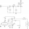
use the attached circuit. It works in the simulation and so it should do in a real circuit. (Compare the contactors of the relay in the ON and OFF position. The relay is animated.)

Use an NPN-transistor and a 9.1V zener diode. You might try an 8.2V zener as well. Using a 9.1V zener the relay voltage is between 12 and 13V.

Don't omit the free wheeling diode across the relay coil to avoid frying of the transistor.

Boncuk
 

Attachments

  • LAMP-OFF.gif
    LAMP-OFF.gif
    12.9 KB · Views: 113
  • LAMP-ON.gif
    LAMP-ON.gif
    12.9 KB · Views: 111
Correction,

the diode is useless as drawn. :)

Connect it that way.

Boncuk
 

Attachments

  • LAMP-ON.gif
    LAMP-ON.gif
    14 KB · Views: 117
Correction,

the diode is useless as drawn. :)

Connect it that way.

Boncuk

Got it. Hero taught me about that well placed diode. But unless you hadn't pointed it out I wouldn't have noticed. Thanks.

My apology's. I should have explained the 2 circuits and my intentions.

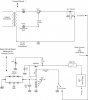
Mainly the top circuit is my re-creation of your buffer circuit. But, using my relay. I built the circuit on the bottom now I'm hoping your buffer circuit can latch the (cc1124-nd relay) and pull the 557b to ground and latching the 2nd relay.

In this drawing the ( 5v 300ma ) is coming from the source pin on a special parallel port built by the manufacturer of some equipment.

I was hoping the buffer circuit with my relay in it would work.


So, I have done the correction on the rectifier and removed the switch to show the voltage coming from my equipment if I push a button on or off in the software I get the source voltage High/low.

This is my first circuit here on the site. When it comes to this I'm a fish in a bath tub going round and round.

Lots to learn.

Thank you

kv
 

Attachments

  • Relay and Buffer circuit.jpg
    Relay and Buffer circuit.jpg
    31.2 KB · Views: 113
Hi Kv,

it doesn't really matter if the switch I used in my schematic is a switch or a relay. The function remains the same. (Switch or relay closed = OFF)

Please be aware of the odd values of resistors and capacitors you used in your design. You will most likely not be able to get parts like these.

Instead of 4K I used 3K9 (standard E12 value) and instead of 110nF I used 100nF.

A DC smoothing electrolytic cap of 100µF instead of 10µF won't be a mistake.

Regards

Boncuk

So, I do not use your (first) Buffer schematic and instead I should use this one.

If so, how do I use the 5v supply coming from my equipment.

Do I directly use a mosfet with the 5v supply switching it on and off.

Confused.

But still needing clarification.

Thank you.

kv
 
Back to the drawing board...........

Ok, so I thought about your circuit and decided that maybe I could pull this off.

The lower Circuit has 12vdc on the board I plan to use it and apply it to an Isolation transformer. Then I also began to look at the circuit and thought maybe with the control voltage it could pull in the transistor 2n2222.

If so do I keep it NPN or change to PNP.

Thanks I hope you can look at it.

I'm also open for suggestions.

kv
 

Attachments

  • Relay circuit revised.jpg
    Relay circuit revised.jpg
    38.4 KB · Views: 117
I was thinking I could pick one out myself but I should have known it would be more complicated.

I have a 5vdc 400ma supply from a status Pin on a parrellel port. I have a voltage I intend to pull to ground using Isolated relay contacts.

The relay's I have been looking at are bigger than the supply voltage I want to use.

Any suggestions.

kv

hi kv, ref your PM.

If I read the first post correctly , I think what you are saying is:

You want to switch a relay ON, using the 5V [ 400mA rated] supply from a device port pin.

The contacts on the relay you switch ON, will then switch ON another device that has a higher voltage and current.

Am I close.?:)

Um ya. I think ?

kv:p
 
Last edited:
Hi KV,

I've not read the whole thread and to be honest I don't want to.

I've just read the first post and briefly skimmed through it.

The circuit in your last post doesn't appear to work.

The 120VAC part looks like a transformerless power supply which will blow up as there's nothing to limit the current.

What's the isolation transformer with +5V and +12V doing at it's secondary?

I don't know why on earth you're using a 110nF capacitor and 4k diode when standard values such as 3k9 and 100nF are near enough.

Sorry but this doesn't make much sense to me. I'm sure this has probably been discussed before but why not just use a relay?
 
Last edited:
I've not read the whole thread and to be honest I don't want to.

I've just read the first post and briefly skimmed through it.

The circuit you're posted doesn't appear to work.

The 120VAC part looks like a transformerless power supply which will blow up as there's nothing to limit the current.

What's the isolation transformer with +5V and +12V doing at it's secondary?

I don't know why on earth you're using a 110nF capacitor and 4k diode when standard values such as 3k9 and 100nF are near enough.

Sorry but this doesn't make much sense to me. I'm sure this has probably been discussed before but why not just use a relay?

duffy said that and I should just do it. But bancuk said I needed a buffer ? after that I think he re-drew my other circuit or something. Now I'm all confused again.

I built pre-fab. And I guess if I pull the relay in it will burn eventually. But when I manually pulled it in it worked.

So, I figured now all I need is a relay and well you can see what happend.


kv
 
You have to be sure before I can suggest a solution.:rolleyes:

What are you wanting to switch ON with the relay contact.?

The bottom circuit. But, I think hero is saying it will just fry anyways the way it's hooked up. So I guess I should build another board the way bancuk is showing me.

But I still need to control it from my port pin 2 with a reliable circuit.
 
The bottom circuit. But, I think hero is saying it will just fry anyways the way it's hooked up. So I guess I should build another board the way bancuk is showing me.

But I still need to control it from my port pin 2 with a reliable circuit.

hi kv,
Like to help if I can.
Im not interested in previous suggestions, just answer my posted questions.:)

What are you wanting to switch ON, ie whats the end result you want.?
 
hi kv,
Like to help if I can.
Im not interested in previous suggestions, just answer my posted questions.:)

What are you wanting to switch ON, ie whats the end result you want.?

Ok, I need to turn on a light. My circuit on the bottom is the one I want to do that with by closing the base of Bc557.


Thank you for your response.


kv
 
Ok, I need to turn on a light. My circuit on the bottom is the one I want to do that with by closing the base of Bc557.


Thank you for your response.


kv

Ok.

You want a relay like the type in this attachment, with the 5V coil.

You connect the relay coil across the +5V [400mA rated] and 0V.

Connect your light and mains supply in series with the normall open relay contact.

Do you follow OK.?
 

Attachments

  • HRMseries.pdf
    275.5 KB · Views: 106
  • esp02 Feb. 08.gif
    esp02 Feb. 08.gif
    12.9 KB · Views: 118
Last edited:
Ok.

You want a relay like the type in this attachment, with the 5V coil.

You connect the relay coil across the +5V [400mA rated] and 0V.

Connect your light and mains supply in series with the normall open relay contact.

Do you follow OK.?

Ok. yes

I have no way to see the PDF I was working cleaning up old programs. I will download another viewer.
 
Thank you everyone. Sorry for the rants.

:D
Download the free Foxit Reader

Foxit Software - Downloads

Damn your post was to late.


Geez, I swear I could Kill for a better operating system.


\\Microsoft, I hate you.\\


I took another hit when the auto updater ? which by the way is not supposed to even look or install an update until.......................... freeeeeking 3:00am in the Gd.....Dm morning.................... freaking hell.

Still ranting : pause :

Ok, done.


Thanks, eric

The relay will do nicely.


I got a relay............. I got a relay today hey hey. ya:D


kv:)
 
Status
Not open for further replies.

Latest threads

New Articles From Microcontroller Tips

Back
Top