Electro Tech is an online community (with over 170,000 members) who enjoy talking about and building electronic circuits, projects and gadgets. To participate you need to register. Registration is free. Click here to register now.
Welcome to our site! Electro Tech is an online community (with over 170,000 members) who enjoy talking about and building electronic circuits, projects and gadgets. To participate you need to register. Registration is free. Click here to register now.
I've got some similar sockets for one of my projects (used as audio connectors).
This is without a plug:
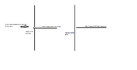
And this is with a plug - the contact "arms" across the top are lifted away from the near side contacts, breaking the connection from side-to-side. The near side parts are nowhere near the plug, there is no connection anywhere from them, like this.
(The far connections then go from the far side, through the plug contacts - but you don't need to do anything with the plug wiring, to just use the switch action).
The type in the first thing I posted would be better if you can find them, as they have proper solder tags for wires, but I could not find those on Amazon. These with the small pins are really...
The situation here is i have a wire out from ignition coil where i have to interfere the supply through external wire, which is when i plug the wire the connection should stop supply and when i remove the wire it should pass the supply, i wonder how the above given connectors work,
Just use the switching contacts and ignore any extras & the plug contacts.
eg. With the jack socket, use the contacts at one side for the power in and the other side for the power out.
When you put a jack plug in the socket, it will disconnect the two sides from each other.
Just use the switching contacts and ignore any extras & the plug contacts.
eg. With the jack socket, use the contacts at one side for the power in and the other side for the power out.
When you put a jack plug in the socket, it will disconnect the two sides from each other.
I've got some similar sockets for one of my projects (used as audio connectors).
This is without a plug:
And this is with a plug - the contact "arms" across the top are lifted away from the near side contacts, breaking the connection from side-to-side. The near side parts are nowhere near the plug, there is no connection anywhere from them, like this.
(The far connections then go from the far side, through the plug contacts - but you don't need to do anything with the plug wiring, to just use the switch action).
The type in the first thing I posted would be better if you can find them, as they have proper solder tags for wires, but I could not find those on Amazon. These with the small pins are really made to mount in a circuit board.
This site uses cookies to help personalise content, tailor your experience and to keep you logged in if you register.
By continuing to use this site, you are consenting to our use of cookies.