tariq7868
New Member
Roft It's all a cover up you would think with any thing could be uncovered. Out of 109,391 smart people I bet you could get what you need to no about any thing. And when that happens some one going to get Mad
And one more thing this is not a paper like the Knoxville News Sentinel
It's form Forms have buddy's talk about a buddy's make a buddy mad.
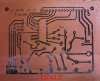
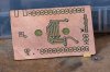
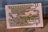
This thread should be only about DIY Toner Transfer Paper (cheap and easy))
And all will be happy
I don't see any thing in the title about Pulsar paper.? I think is said
Cheap easy DIY Toner Transfer Paper.
i am with 'be80be' ...
anyway.. i am also going try white (artwork) Glue trick..
Last edited: