Continue to Site

Welcome to our site!

Electro Tech is an online community (with over 170,000 members) who enjoy talking about and building electronic circuits, projects and gadgets. To participate you need to register. Registration is free. Click here to register now.

  • Welcome to our site! Electro Tech is an online community (with over 170,000 members) who enjoy talking about and building electronic circuits, projects and gadgets. To participate you need to register. Registration is free. Click here to register now.

Advice on multiplexing ten 7-segment display

Status
Not open for further replies.

taengi

New Member
Hi all eletronics seniors,
I am new here. I am trying to multiplex ten 7-segment common cathode.

here is my circuit explanation:
assume that each segment need 5mA to turn on (forward biased voltage = 1.7), 10 digit means I need 50mA, right?

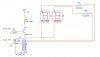
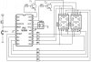
I have used seven 2N2222A as 7-segment drive. the collector is to 9Vcc with 140ohms [(9v - 1.7v)/50mA]. the output also to 7-segment [ie. when BJT off, segment lit on; when BJT ON, segment off]. The emmitter is to GND. The base is connected to PIC output[2.5v] with a diode in series with resistor of 2.2kohm [500uA]. The diode is to protect the PIC from damage if the BJT damaged. My questions are:

1. I run simulation and it seems ok.but when i build the circuit, i spoiled every IC link to it including PIC. By the way, i used 4017 counter with 7404 inverter to turn each digit ON/OFF. Is it because I didn't put heat sink at the common cathode of 7-segment?

2. 500uA on base current is it too big? will it spoiled the BJT?

3. I found that even when BJT ON [ segment should be OFF ], but i can still see the dim color. is there anyway to make it off?

4. I have tried to connect the emitter of each BJT to each 7-segment, it turns out to be very dim..[because i don't want to invert software coding]. I thought by making sure each segment have 5mA would be sufficiently bright enough?

5. PortA of my 877 seems to source 2.5v instead of 5v, why is that so? I am confused over it.

I really apreciate your feedbacks.
 
Although the design below is for a PLD it can be used on a PIC as well. you can expand it to 10 segments of course.

First, you drive the Common Cathodes with 10 transistors. NOT drive the segments with 7 transistors at 9v... There's no reason to use more than 5v in most < 1.8" LEDs

In a nutshell.

You can only light ONE CC display at a time (any number of segments is ok) So you must turn on your 2n2222 only one at a time (muxing) and you must refresh the complete display constantly at better than 40hz (some people still see flicker at that speed, I often use 60hz)

If you dont want to mux but drive the displays directly then you simply don't have enough I/O on a 16F877. You should consider a decoder IC.

I like to use a technique called charlieplexing, very I/O efficent but requires a little bit of fancy software. You can see an example of the hardware (Zebra) on my site.
 

Attachments

  • 7segment.png
    7segment.png
    49.6 KB · Views: 1,768
I suggest you post a section of your circuit (we don't need all ten displays), just one display section and the PIC.

It's rather confusing mentioning counters and a 16F877?, what are they all doing?, the 16F877 should easily be able to do it all.

You don't need diodes from the PIC to the bases, the resistor will limit any current problems, but again we need to see the circuit.
 
Hi,
It sounds like youre going about it all wrong. Use 7 current limiting resistors to each of the 7 segments, connect the segments to all the digits (a-a-a-a-a-a-a-a-a-a, b-b-b-b-b-b-b-b-b-b, etc) in parallel, and use 10 drive transistors on each of the 10 common cathodes. Multiplex the display through the drive transistors.
You can (should) use your PIC to count AND multiplex. Maybe use a BCD to 7-seg decoder driver (ie, cd4511) to save I/O if you need to.
I dont get how you calculated 500uA. Dont forget about the voltage drop from the diode that you dont need! Keep it SIMPLE! Then improve upon it.
 
I use 4017 to select each digit out of 10 digits. RB1 from 877 connected to Pin14 of 4017 will ON/OFF to enable the ring counter. this would save my 877 I/O ports.

500uA is calculated from Ic/HFE [50mA/100], is that correct. I've read some of your previous thread regarding display so I come up with this design.

I use transistor to drive each segment coz the output from PIC doesn't sufficient to lit on the segment [approx 2.5v] which is a wonder to me as well coz I expected aprrox 4.5 ~ 5 v. I also want to reduce the use of BJT, so that's why I use 4017 to select 10 digit instead of another 10 transistors.
 

Attachments

  • try.jpg
    try.jpg
    34.8 KB · Views: 1,607
You don't need R2.

The transistor is configured as an emitter follower.

So connect the base directly to the PIC, transfer R1 to the emitter side and connect the collector to Vcc.

Neither do you need the counter as the PIC can do the counting - provided that there are enough i/o available.
 
I (still) dont know what youre trying to do, but the '877 has 33 I/O pins!!! 7 for the segments + 10 for the drive transistors = 27. You'll still have 6 I/O left to hook up your flux capacitor and warp drive.
The conventional way to do this is as I said in my earlier post. Is this strictly a counter? What are you trying to do?????
 
Whoops, this didnt work the first time...
 

Attachments

  • pic_mux_display.jpg
    pic_mux_display.jpg
    38.3 KB · Views: 1,814
thanks guys for all your replies.

Hi hyeneddy,
ooh..i forgot to mention that I've used other I/O pins for other purposes. 8 for matrix keypad, 4 for leds, and buzzer...most of this applications works well...except for the 10 digits display which turns out to be very dim.

To clarify everything, I wish to use one 4017 to replace 10 transistors to select each digit at a time. That is what I am trying to do. at the 10 output pins of 4017, only one will turn on each time, it is like when digit 1 is on, others are off, when digit 2 is on, all others are off and so on. The 4017 is activated by a clock pulse, which is taken care by PIC software. Does this clarify everything?

BTW hyedenny, how do you run simulation on PIC? I mean where do you find a software that can simulation your circuit using PIC?


hi ljcox,
is it ok to remove base resistor? I thought R2 is to limit the current and prevent PIC from damaged?
I've tried to placed R1 on emitter side and connect collector to Vcc. the segment are then connected to emitter on simulation and practical, the result is still very dim.
 
taengi said:
The 4017 is activated by a clock pulse, which is taken care by PIC software. Does this clarify everything?

If you use a counter instead of a decoder to select the display digit, a glitch somewhere, from the power line or from allmighty could increase the count of the 4017 by one but the PIC would not know about it.

All the displayed data will then be shifted and wrong. You can avoid this by resetting the 4017 after each scan.
 
Thanks eblc 1388, I did face this problem like when I lock digit 6 to display, the random numbers appear instead of 0 even if I didn't press any button from keypad. so what you mean is to reset it every time the sequence run till the 10th digit?
 
taengi said:
Thanks eblc 1388, I did face this problem like when I lock digit 6 to display, the random numbers appear instead of 0 even if I didn't press any button from keypad. so what you mean is to reset it every time the sequence run till the 10th digit?

You starts with digit powered by 4017 Q0 output, then you moves on to the next digit by clocking the 4017. After the complete scan of ten digits, the 4017 output should rollover back to Q0. However, you cannot trust that it will because of the problem I mentioned earlier.

Therefore, you have to use the PIC to reset the 4017 to Q0, although 99.9999% of time it is already at Q0 state.
 
Correct me if I am wrong.

one segment need 5mA to be bright. so two digits required 10mA.

how about 10 digits? does it mean I need 50mA at the collector? how about base current? is the base current calculated by Ic/HFE?

another thing is, on the 2N2222A datasheet, it stated that Ibl [base current] max is 20nA, does it mean I cannot supplied more than 20nA to the base of 2N2222A?
 
taengi said:
Correct me if I am wrong.

one segment need 5mA to be bright. so two digits required 10mA.

how about 10 digits? does it mean I need 50mA at the collector? how about base current? is the base current calculated by Ic/HFE?

Yes, you need to pulse each LED with 50mA (for your example), as they are each on 10% of the time they effectively get 5mA each.

You don't need to worry about base current, however your positive driving method is very poor - it's best if you use PNP transistors from the positive rail, but that would require NPN's to drive them (due to your 9V supply rail). As it stands, with the NPN transistors, the maximum voltage to the displays is only 4.3V, so you're wasting your 9V supply anyway!. Also the 140 ohm resistor in the collector isn't a very good idea, and will make it difficult to calculate the current to the display - moving it to the emitter would make more sense.

another thing is, on the 2N2222A datasheet, it stated that Ibl [base current] max is 20nA, does it mean I cannot supplied more than 20nA to the base of 2N2222A?

No, ignore everything about the base! - except I would suggest you use something like 470 ohm resistors between the PIC pins and the bases, to give better base drive.
 
Not a very good example though?, the 10K base resistors are too large, and the 100 ohm resistors are in the wrong place - simply moving them to the collectors of the transistors, and lowering the base resistors, will make the circuit work properly.

However, a considerable improvement would be removing the 100 ohms all together, and adding limiting resistors in the segment connections instead (from PortC of the PIC).
 
taengi said:
I mean where do you find a software that can simulation your circuit using PIC? The MPLAB software which can be downloaded free of charge from Microchip has a simulation function.
hi ljcox,
is it ok to remove base resistor? I thought R2 is to limit the current and prevent PIC from damaged?
I've tried to placed R1 on emitter side and connect collector to Vcc. the segment are then connected to emitter on simulation and practical, the result is still very dim.
When the resistor is on the emitter side, you do not need a base resistor.
This configuration is called an emitter follower. The base current will only be a large it needs to be according to the callector current. Ib = Ic/hFE. so, for example, if Ic = 20 mA and hFE = 100, then Ib = 0.2 mA.

As I think Nigel pointed out, you need 50 mA because of the x10 muxing. I estimate that the collector current is about 15 mA assuming they are red displays and that there is only one LED per segment. However, some displays have 2 LEDs per segment which would make the current even lower.

I suggest that you do a static test (ie. steady current, no pulsing) and measure the current through a segment that is necessary to give the required brightness and then measure the voltage across the segment at that current. Report the figures to us so we can calculate the resistor value for you.
 
ljcox said:
When the resistor is on the emitter side, you do not need a base resistor.

But there's a difference between 'need' and 'good practice', while the base resistor won't affect the performance of the circuit, it's there to protect the PIC if the transistor goes S/C.

As an added bonus, the resistors also probably simplify PCB layout, avoiding the need for wire links or double sided boards.
 
Status
Not open for further replies.

New Articles From Microcontroller Tips

Back
Top