Hi guys and girls!
I found a thread on this topic on the forum, but it does not answer a couple of questions I have. I am quite a newbie in the world of electronics and that will probably be evident from what I did. So here goes :
The project is a pump controller. It uses a processor with built-in HTTP to control pumps via web interface. The project also has a 433 MHz receiver that can receive a dam's water level information, which is then interpreted by the processor. The processor can then decide to start certain pumps based on whatever criteria is provided. The processor activates AC relays through 2N2222A transistors.
Everything works great until I actually connect a load to the relays and try to switch them on. Sometimes it works, but a lot of the time it restarts the processor. I assume it is because of the noise generated by the AC being switched that somehow travels all the way back to my processor. It doesn't matter if the load is resistive (incandescent light bulb) or inductive (another relay).
Now, I think my biggest problem comes from the fact that I have a ground plane covering all of my unused board real-estate (even under the relays). Could this be the biggest problem here?
Then, the biggest question. Can I fix this without changing the board (eg. soldering caps onto certain pins on the underside of the board)?
This is a prototype board for the project, but I would like to make certain that everything is perfect before submitting the final board layout to the manufacturers.
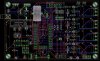
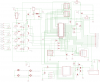
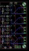
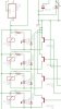
I have included excerpts from my board layout and schematic. All the spaces between tracks is ground plane (on both sides). K1 - K4 are the relays.
I found a thread on this topic on the forum, but it does not answer a couple of questions I have. I am quite a newbie in the world of electronics and that will probably be evident from what I did. So here goes :
The project is a pump controller. It uses a processor with built-in HTTP to control pumps via web interface. The project also has a 433 MHz receiver that can receive a dam's water level information, which is then interpreted by the processor. The processor can then decide to start certain pumps based on whatever criteria is provided. The processor activates AC relays through 2N2222A transistors.
Everything works great until I actually connect a load to the relays and try to switch them on. Sometimes it works, but a lot of the time it restarts the processor. I assume it is because of the noise generated by the AC being switched that somehow travels all the way back to my processor. It doesn't matter if the load is resistive (incandescent light bulb) or inductive (another relay).
Now, I think my biggest problem comes from the fact that I have a ground plane covering all of my unused board real-estate (even under the relays). Could this be the biggest problem here?
Then, the biggest question. Can I fix this without changing the board (eg. soldering caps onto certain pins on the underside of the board)?
This is a prototype board for the project, but I would like to make certain that everything is perfect before submitting the final board layout to the manufacturers.
I have included excerpts from my board layout and schematic. All the spaces between tracks is ground plane (on both sides). K1 - K4 are the relays.
Attachments
Last edited: