Has anyone any experience with the**broken link removed** Function generator IC, Im prototyping a function generator design based on the XR2206, but Im having trouble with distortion on the positive peaks of sine o/p. The distortion is present for the full range of frequencies and is not affected by DC offset or amplitude... .Adjusting the symmetry (22k pot) makes no difference either.
+VCC = 5v and -VCC = -5V
**broken link removed**
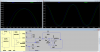
Sine @ Pin 2
**broken link removed**
Zoomed in on the peak...
**broken link removed**
+VCC = 5v and -VCC = -5V
**broken link removed**
Sine @ Pin 2
**broken link removed**
Zoomed in on the peak...
**broken link removed**