Continue to Site

Welcome to our site!

Electro Tech is an online community (with over 170,000 members) who enjoy talking about and building electronic circuits, projects and gadgets. To participate you need to register. Registration is free. Click here to register now.

  • Welcome to our site! Electro Tech is an online community (with over 170,000 members) who enjoy talking about and building electronic circuits, projects and gadgets. To participate you need to register. Registration is free. Click here to register now.

WRT54G v1.0 - No LEDs or Power

Status
Not open for further replies.
If youve been around for awhile, chances are you've seen my other thread(s) about it. I came across the board the other day, and now that I have a bit more experience, I figured I'd give it another shot.

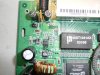
The wall wart puts out ~6.9v, so it's pretty unregulated. The top chip is an RT9202 Single Synchronous Buck PWM DC-DC Controller, but I dont know what the bottom chip is - it says this on it:

9936
Δ31B9M

Anyways, as you can see in the picture, one one side of the chip, I have power, but on the other side, nothing. This could be why I have no power on the rest of the board.

If you have any ideas, need more info, or want to talk to me on MSN (so you can say try this and I can try it and tell you what happens in real-time), let me know. I would greatly appreciate any input!

EDIT Ignore the flux residue on CA14, I touched it up with a soldering iron (along with the rest of the points in the area) to make sure there were no cold joints.
 

Attachments

  • P1000913.JPG
    P1000913.JPG
    902.8 KB · Views: 307
Last edited:
I don't know.

Did you measure the voltage at the other pint?

Perhaps if you trace out that section of the circuit it might give you a clue.

As a total guess it's likely to be an op-amp or some sort of voltage reference.
 
No suggestions, ideas, anything? Didnt think it would be that difficult for you guys to figure out ;)

hi,
That large inductor [enamalled copper wire] near the bottom of the picture, the soldering looks as dry as old boot...:rolleyes:

Scrape off the enamel from the wire and resolder to the pcb.
 
Last edited:
Here is a high-res shot of the area with the mystery chip removed. Hopefully where the traces lead will help someone more intelligent than I recognize what kind of chip it is, what it does, or what kind of circuit Im looking at.
**broken link removed**
 
Look at Fairchildsemi or Vishay Si9936 dual MOSFET. 4R7 in series with each gate, wired as totem pole, perfect match.
 
Would anyone be able to order one for me, and mail it up here? Mouser wants $15 just to ship two chips to Canada, and I know it sure as hell doesnt cost that much to drop a couple chips in an envelope.

Mouser # 781-SI9936BDY-T1-E3 (The Fairchild one is obsolete and Digi-key doesnt stock them).
 
Last edited:
You can probably use Si4834. I found 20 pcs on ebay for $4.50 plus $1.35 shipping. Send him an email to see if he ships to Canada. If he won't, send me a PM.
 
:( Didnt fix it. I still have no voltage on the output side of the MOSFETs. However, I found that when I pressed down on the PWM IC with the tip of my multimeter probe, something on the board started buzzing! When I let go of the chip the buzzing went away. This time I pressed a bit harder and it stayed buzzing when I let go, so I unplugged the router right away!

Could the PWM chip be bad? Any way to tell without buying another one? While the experimenting is fun, I have no use for the other 19 mosfet chips, and if I have to order bulk PWM chips, I will have no use for them either.
 
Last edited:
It is possible that the PWM chip is bad (it's a richtek part, which is garbage - at least imho). You said the input is around 6.9V - the maximum allowable input voltage on the RT9202 is 7V. It's never good to run a PWM controller IC near its max input level - especially if the same rail is being used as the input to the down coverter.

What you need to do is remove the output inductor (which you've already done) and place a voltage on the output of the PWM regulator that is the level that the regulator is supposed to be regulating to. If everything works like that, then you know you have a problem with the regulator and that can then be dealt with. If nothing works or excessive current is being drawn from your external power supply, then something downstream of the regulator is hosed.

What is the output level of the regulator? If you do not know, you can figure it out from the board. Pin 6 of the RT9202 is the feedback pin. There should be two resistors tied to this pin - one will have the other end tied to the regulated output (call this Rfb) and the other resistor will have its other end tied to ground (call this Rp). The regulated output voltage will be:
Vout = 0.8*(1+Rfb/Rp)
Its not easy to tell, but it looks like Rfb would be RF1, which is 330 ohms and Rp would be R3 which is 100 ohms. This would yield an output of 3.4V - which sounds about right for 3.3V logic, etc. Double check, though - the picture has shiny spots that make it hard to see the copper traces.
 
Status
Not open for further replies.

Latest threads

New Articles From Microcontroller Tips

Back
Top