tuxamd
New Member
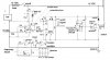
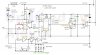
I need help finding the parts to and figuring out how to make this circuit. It's for a simple experiment I want to try out, and it's basic function is a pulse generator. However the last time I made any circuits was years ago and they were simple never requiring any ICs and parts of that sort.
What I'm trying to figure out is the following:
1. What is the whole box around the TC4420CPA and what it is in the first place.
2. By the word throttle it says 100k. I'm assuming that's a 100k poteometer? I know the designer of this didn't do a good job drawing this but it's up to me to figure out where that poteometer should go. I don't see any specific markings for it's location.
3. What kind of fuse do I need for where it says 12V DC fuse? The author didn't specify any amperage or anything. I'm assuming this is a pretty weak circuit and doesn't require too much power, and also thinking about the power of a typical car battery, does anyone have any guesses for what kind it should be?
4. The 3 triangles for CD4069 is an IC chip 4069 with it's different pins as marked in the diagram right? Does this also apply for LM741?
5. At the bottom of the design there are a number of capacitors. I thought all capacitors are measured in uf? What's u and pf?
I know these questions may seem pretty stupid to some but I would appreciate any help as I don't know too much about electronics and would like to build this design for an experiment. Once I finish it I'll share more details on it and my results.
And one last question is where would you people recommend I buy all of these parts from? I believe Mouser Electronics is the best and has them all, however their ordering system is the most confusing I've ever seen. It's hard to find any parts on their website and even harder to order them.
Update:
So far the list of parts I have I need to get are:
Misc:
1 Fuse 12V DC 5.5A
504-AGA-6 - https://www.electro-tech-online.com/custompdfs/2005/04/399.pdf
44FH052 - https://www.electro-tech-online.com/custompdfs/2005/04/1543.pdf
1 Power Supply 12V DC 5A
418-CFM60S120 https://www.electro-tech-online.com/custompdfs/2005/04/1340.pdf
1 Power LED
1 N4007 Diode
625-1N4007 - https://www.electro-tech-online.com/custompdfs/2005/04/315.pdf
4 Dipswitches
571-14358025 - https://www.electro-tech-online.com/custompdfs/2005/04/1080.pdf
Poteometers:
1 2k (do I need a linear or audio?)
31JN302 - https://www.electro-tech-online.com/custompdfs/2005/04/451.pdf
3 20k
688-RK09D1130A0Z - https://www.electro-tech-online.com/custompdfs/2005/04/453.pdf
Resistors
2 10k
660-CF1/4L103J - https://www.electro-tech-online.com/custompdfs/2005/04/424.pdf
4 1k
660-CF1/4L - https://www.electro-tech-online.com/custompdfs/2005/04/424.pdf
Transistors & ICs
1 IRF510 (The author wrote iFr while you state iRf, though I'd believe you guys more)
512-IRF510A - https://www.electro-tech-online.com/custompdfs/2005/04/346.pdf
datasheet - https://www.fairchildsemi.com/ds/IR/IRF510A.pdf
1 TC4420CPA
579-TC4420CPA - https://www.mouser.com/catalog/621/202.pdf
datasheet - **broken link removed**
1 NE555
511-NE555D - https://www.mouser.com/catalog/621/207.pdf
datasheet - https://www.st.com/stonline/books/pdf/docs/2182.pdf
1 LM741
511-UA741CN - https://www.mouser.com/catalog/621/232.pdf
datasheet - https://www.st.com/stonline/books/pdf/docs/5304.pdf
1 CD4069
512-CD4069UBCM - https://www.mouser.com/catalog/621/182.pdf
datasheet - https://www.fairchildsemi.com/ds/CD/CD4069UBC.pdf
Capacitors:
1 10uf
647-UVR1C100MDD - https://www.mouser.com/catalog/621/487.pdf
3 .1uf
647-UVR2A0R1MDD - https://www.mouser.com/catalog/621/487.pdf
1 1uf
647-UVR1H010MDD - https://www.mouser.com/catalog/621/487.pdf
2 .01uf - I can't find anything this low in the normal shape on that website
all of them seem to only be the relaly tiny surface mount capacitors. Does anyone know about this? Is it safe to use the small surface mount ones? Won't my soldering iron burn them?
1.03uf
1 3300pf
Am I missing anything or are any of those wrong?
What I'm trying to figure out is the following:
1. What is the whole box around the TC4420CPA and what it is in the first place.
2. By the word throttle it says 100k. I'm assuming that's a 100k poteometer? I know the designer of this didn't do a good job drawing this but it's up to me to figure out where that poteometer should go. I don't see any specific markings for it's location.
3. What kind of fuse do I need for where it says 12V DC fuse? The author didn't specify any amperage or anything. I'm assuming this is a pretty weak circuit and doesn't require too much power, and also thinking about the power of a typical car battery, does anyone have any guesses for what kind it should be?
4. The 3 triangles for CD4069 is an IC chip 4069 with it's different pins as marked in the diagram right? Does this also apply for LM741?
5. At the bottom of the design there are a number of capacitors. I thought all capacitors are measured in uf? What's u and pf?
I know these questions may seem pretty stupid to some
but I would appreciate any help as I don't know too much about electronics and would like to build this design for an experiment. Once I finish it I'll share more details on it and my results.And one last question is where would you people recommend I buy all of these parts from? I believe Mouser Electronics is the best and has them all, however their ordering system is the most confusing I've ever seen. It's hard to find any parts on their website and even harder to order them.
Update:
So far the list of parts I have I need to get are:
Misc:
1 Fuse 12V DC 5.5A
504-AGA-6 - https://www.electro-tech-online.com/custompdfs/2005/04/399.pdf
44FH052 - https://www.electro-tech-online.com/custompdfs/2005/04/1543.pdf
1 Power Supply 12V DC 5A
418-CFM60S120 https://www.electro-tech-online.com/custompdfs/2005/04/1340.pdf
1 Power LED
1 N4007 Diode
625-1N4007 - https://www.electro-tech-online.com/custompdfs/2005/04/315.pdf
4 Dipswitches
571-14358025 - https://www.electro-tech-online.com/custompdfs/2005/04/1080.pdf
Poteometers:
1 2k (do I need a linear or audio?)
31JN302 - https://www.electro-tech-online.com/custompdfs/2005/04/451.pdf
3 20k
688-RK09D1130A0Z - https://www.electro-tech-online.com/custompdfs/2005/04/453.pdf
Resistors
2 10k
660-CF1/4L103J - https://www.electro-tech-online.com/custompdfs/2005/04/424.pdf
4 1k
660-CF1/4L - https://www.electro-tech-online.com/custompdfs/2005/04/424.pdf
Transistors & ICs
1 IRF510 (The author wrote iFr while you state iRf, though I'd believe you guys more
)512-IRF510A - https://www.electro-tech-online.com/custompdfs/2005/04/346.pdf
datasheet - https://www.fairchildsemi.com/ds/IR/IRF510A.pdf
1 TC4420CPA
579-TC4420CPA - https://www.mouser.com/catalog/621/202.pdf
datasheet - **broken link removed**
1 NE555
511-NE555D - https://www.mouser.com/catalog/621/207.pdf
datasheet - https://www.st.com/stonline/books/pdf/docs/2182.pdf
1 LM741
511-UA741CN - https://www.mouser.com/catalog/621/232.pdf
datasheet - https://www.st.com/stonline/books/pdf/docs/5304.pdf
1 CD4069
512-CD4069UBCM - https://www.mouser.com/catalog/621/182.pdf
datasheet - https://www.fairchildsemi.com/ds/CD/CD4069UBC.pdf
Capacitors:
1 10uf
647-UVR1C100MDD - https://www.mouser.com/catalog/621/487.pdf
3 .1uf
647-UVR2A0R1MDD - https://www.mouser.com/catalog/621/487.pdf
1 1uf
647-UVR1H010MDD - https://www.mouser.com/catalog/621/487.pdf
2 .01uf - I can't find anything this low in the normal shape on that website
all of them seem to only be the relaly tiny surface mount capacitors. Does anyone know about this? Is it safe to use the small surface mount ones? Won't my soldering iron burn them?
1.03uf
1 3300pf
Am I missing anything or are any of those wrong?