Continue to Site

Welcome to our site!

Electro Tech is an online community (with over 170,000 members) who enjoy talking about and building electronic circuits, projects and gadgets. To participate you need to register. Registration is free. Click here to register now.

  • Welcome to our site! Electro Tech is an online community (with over 170,000 members) who enjoy talking about and building electronic circuits, projects and gadgets. To participate you need to register. Registration is free. Click here to register now.

Wiring/symbol help...

Status
Not open for further replies.

cup888

New Member
I want to power a small heater 2kw in my bedroom with this wireless thermostat. Because its affordable and has very fine 0.25C heat sensing switching. I'm having trouble understanding how to wire it correctly.


Question 1)
Is this able to be wired directly to the heater? its a 2kw heater so would need 10a 230V UK mains.

Question 2)
For example I can't understand what this means:
16 amp relay switching
RX Rating Max: 16 (5) A SPST

Question 3)
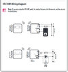
following this wiring diagram
(attached)

to have the heater powered maybe I use the bottom image. But...
It says Max 16 (5) A . I dont know what voltage it handles/outputs, what is the (5) ???
The black triangle in circle & M in circle with two arrows. What do both these symbols mean???

Question 4)
In other words I'm confused about the (5) - maybe it means 16A 5V
And maybe the symbols are a low voltage 5V switch for a larger Volt appliance.
So basically can this be wired straight through or would it require an extra switch before the heater ???

Replies appreciated.
Thanks.
 

Attachments

  • Untitled.jpg
    Untitled.jpg
    61.7 KB · Views: 201
Question 4)
In other words I'm confused about the (5) - maybe it means 16A 5V
And maybe the symbols are a low voltage 5V switch for a larger Volt appliance.
So basically can this be wired straight through or would it require an extra switch before the heater ???
At a guess I would suggest it's actually 16A AC and only 5A DC, contacts are commonly greatly de-rated for DC.

As it's 16A it should be fine, but don't get too impressed by the supposed 0.25 degree specification :D
 
Some relays are rated higher current for switching on than switching off. I found this out the hard way the other day .....

*edit - just noticed it is a single pole single throw - ignore me.
 
Some relays are rated higher current for switching on than switching off. I found this out the hard way the other day .....

*edit - just noticed it is a single pole single throw - ignore me.
You weren't switching DC were you?, it's the OFF which restricts DC, as the arc is sustained as the contacts break - with AC it stops as the AC drops to zero. So you can turn ON high current DC, you just can't turn it OFF :D
 
What do those two symbols on the diagram mean. Any idea? The 'black triangle in circle' & 'M in circle with two arrows below'. What do each of these symbols mean?
 
You weren't switching DC were you?, it's the OFF which restricts DC, as the arc is sustained as the contacts break - with AC it stops as the AC drops to zero. So you can turn ON high current DC, you just can't turn it OFF :D
Yup, found the relays we were about to use weren't suitable at the last minute.

Also had an issue with a DC load which was quite capacitive, inrush caused the 16A terminals to weld closed so ended up with a SSR which was on the edge of it's capacity turning on first with the relay backing it up a second later. Turning off was the reverse, relay off first then SSR off a second later.

Rookie mistake! :D :D :D

As for the inrush, this is a very common issue on high power audio PA gear, using toroidal transformers - the usual technique is a soft start circuit, with a high wattage resistor to limit the initial surge, which is then shorted out by a timed triac. You could obviously do the same with a relay across the resistor as well - or in your example, a resistor in series with the SSR, and the relay shorting them both out (takes the strain off the SSR).
 
I've used the NTC thermistors that are designed for inrush limiting. They have worked well for me when supplying toroidal transformers.

None of the high power amps seem to do that, as I've seen anyway - do they make suitable thermistors?. are they too expensive?, and are they too unreliable?.

You also have the obvious problem that they are very time limited - once it's hot, it's hot (and it's likely to be very hot), and will remain so for an extended period. So once you've plugged it in, you can't move it (and plug it back in) unless you let it cool down first.

Hey Fred, the speaker leads won't reach - move the amp over here - BANG!!!! - why has the fuse blown to bits?.
These were the sort of thermistors that I used:- https://uk.farnell.com/epcos/b57211p0100m301/thermistor-10r-20-ntc-rad/dp/2101618

They certainly solved the problem of transformer inrush tripping the circuit breaker. I never worried about the cool-down time. I've not tested with very short intervals between turning off and turning back on, but I've never blown a fuse in a couple of decades of use.

Much of the inrush was just due to the transformer saturating at turn-on, as I saw issues where there was nothing connected to the transformer secondary.

Thermistors like that were too small for a 10 kVA three-phase transformer which would trip the breaker at turn-on. On that I used wirewound resistors to limit the current. There was a timer relay and a contactor to short out the resistors after half a second or so.
 

Fairly low power ones than?.
https://uk.farnell.com/epcos/b57211p0100m301/thermistor-10r-20-ntc-rad/dp/2101618
They certainly solved the problem of transformer inrush tripping the circuit breaker. I never worried about the cool-down time. I've not tested with very short intervals between turning off and turning back on, but I've never blown a fuse in a couple of decades of use.

Much of the inrush was just due to the transformer saturating at turn-on, as I saw issues where there was nothing connected to the transformer secondary.

Thermistors like that were too small for a 10 kVA three-phase transformer which would trip the breaker at turn-on. On that I used wirewound resistors to limit the current. There was a timer relay and a contactor to short out the resistors after half a second or so.

10KVA three phase is pretty well identical to 3KW single phase, which is what high power amps are taking - and the switch-on surge from toroidal transformers is huge.

The reason I'm familiar with them is because the soft-start circuits commonly fail, the triac either goes short (and blows the fuse every few times you plug it in), or it goes O/C and the resistor fries.
 
I had used inrush thermistors up to about 1 kW. I don't think that the larger ones were available when I fitted the resistors and contactor to the 10 kW transformer. If they were available, I didn't find any.

It's a lot less work to put a thermistor in series than to put together a circuit with a resistor, a triac or a relay, and a timer. It could be that the thermistors are less reliable or have some other problems, so the solution that I found easy for one-offs might not be the best for mass produced devices, but Farnell seem to stock large numbers of the inrush thermistors.

I've repaired a few amplifiers that had soft start resistors and a relay or a triac for normal running. I also repaired a VFD that had a soft start resistor and an IGBT.
 
It's a lot less work to put a thermistor in series than to put together a circuit with a resistor, a triac or a relay, and a timer. It could be that the thermistors are less reliable or have some other problems

Certainly so, in-rush thermistors were notoriously unreliable - it was a common failure in TV's going back to the 1950's at least - more modern sets dropped them entirely, presumably for that reason?. And of course consumption was a LOT less, and simple surge limiting resistors (usually either 4.7 ohm or 10 ohms) were used instead. A thermistor like that is a pretty crude device, and subject to serious thermal changes - they commonly cracked or chipped.

We used to have a draw full of valve TV in-rush thermistors at work, various different ones for different sets :D
 
We had very few failures of this type here in Canada!


Lot's and lot's of failures in the UK, as a workshop engineer I changed relatively few (basically just on sets customers brought in the shop) the outside engineers normally just replaced them in the customers house.

Mostly the effect would be seriously bad purity, and if you took the posistor apart you would find it was cracked or chipped.
 
I have tested several thermostats for winter camping to keep our 15ft camper trailer warm in freezing weather. If the temperature is plus to minus 4 degrees F that is very irritating to be cold 1 minute then too hot 10 minutes later all night long. We wake up feeling like we never slept all night long in 25 F weather.

If thermostat is plus to minus 1 degree F that is very good but a thermostat that accurate can get expensive and be completated you need solid state with 12 volt power supply circuit and 120 volts too.

The thermostat that works best for us is a bi metal thermostat accurate to 2 degrees F. There are no solid state parts. No low voltage circuit. No circuit board. No electronic parts. Very easy to connect thermostat in series with the electric heater. The only moving parts are the bi metal 120v contacts & the temperature dial.

The thermostat that I bought is rated 120/240 vac 15 amps price was $19. I mounted my thermostat next to a wall outlet then wired the thermostat to turn the outlet on & off. All I need to do is plug my electric heater into the wall outlet.

Here is a link to a Robertshaw thermostat on Ebay do your own search to find the correct bi metal thermostat you need. Make is simple & make it work.


s-l500.jpg
 
Last edited:
Status
Not open for further replies.

Latest threads

New Articles From Microcontroller Tips

Back
Top