LondonBoards
New Member
Hi dudes and dudette’s..
Get ready for the old ‘little bit of knowledge is a dangerous thing’…
Iv got a load of motors which we’re going to be scrapped, I saved them and mean to use them some day.. the first one I can use on my lathe, but I need to flip the direction of rotation.
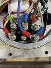
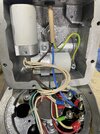
Most motors Iv looked in before have 2 link bars and you flip them around to swap rotation, this motor has just 1 link bar. Iv thought about trying to flip it but feel I may melt something so best to ask.
If anyone could tell me how to do this, it would be greatly appreciated.
It would also be pretty awesome if I could somehow wire it to rotate either direction with the flick of a switch. Iv wired things like electric windows in cars using DTDP switches, is this viable if I get rid of the link bar and wire it instead? If I use a DTDP switch to control direction and have a separate on/off switch, would that be ok
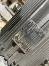
It’s a 1940’s Myford lathe that I rescued from a scrap yard 10yrs ago, part way through restoring it, be great to finally get the thing running.
Iv also got a few other motors, one of which is quite interesting, I’ll make another thread for that when I get a minute to take some pics and workout what I’m doing with it.
Get ready for the old ‘little bit of knowledge is a dangerous thing’…
Iv got a load of motors which we’re going to be scrapped, I saved them and mean to use them some day.. the first one I can use on my lathe, but I need to flip the direction of rotation.
Most motors Iv looked in before have 2 link bars and you flip them around to swap rotation, this motor has just 1 link bar. Iv thought about trying to flip it but feel I may melt something so best to ask.
If anyone could tell me how to do this, it would be greatly appreciated.
It would also be pretty awesome if I could somehow wire it to rotate either direction with the flick of a switch. Iv wired things like electric windows in cars using DTDP switches, is this viable if I get rid of the link bar and wire it instead? If I use a DTDP switch to control direction and have a separate on/off switch, would that be ok
It’s a 1940’s Myford lathe that I rescued from a scrap yard 10yrs ago, part way through restoring it, be great to finally get the thing running.
Iv also got a few other motors, one of which is quite interesting, I’ll make another thread for that when I get a minute to take some pics and workout what I’m doing with it.
Attachments
Last edited:
