Continue to Site

Welcome to our site!

Electro Tech is an online community (with over 170,000 members) who enjoy talking about and building electronic circuits, projects and gadgets. To participate you need to register. Registration is free. Click here to register now.

  • Welcome to our site! Electro Tech is an online community (with over 170,000 members) who enjoy talking about and building electronic circuits, projects and gadgets. To participate you need to register. Registration is free. Click here to register now.

Winding a transformer?

Status
Not open for further replies.
I find it odd that the transformer equation doesn't include current...because I just picked a core of a physical size that I deemed reasonable to have eight of and punched it's cross section in with 8 turns (just enough to be fairly evenly distributed along the toroid) and it's only giving me 710 Gauss with my voltage and frequency requirements (and the equation doesn't ask for current). The core material itself is supposed to be able to handle 8000Gauss-10000Gauss. So either my tolerable physical size is way larger than is magnetically required, or I'm doing something wrong.

I keep seeing the word "window" brought up though and as best as I can tell, it's just the size of the hole in the toroid core? But I'm sure it must have some other more relevent magnetic definition since not all inductors or transformers are toroidal. But everything on Google seems to refer to it as a given, without explaining what it actually is.

Speaking of litz wire, this does't seem that bad:
**broken link removed**

Not entirely sure if it's accurate to figure out the current rating by simply going 13 strands * Current capacity for 30AWG (taking skin effect into account at the frequency of interest). Seems there would be lots of derating since its like bundling wires as well as winding them together. They all seem pretty low current though.
 
Last edited:
Hello again,


Well, once you assume a given core physical size and number of turns you've assumed a given inductance, and once you've assumed a given inductance and a given voltage you've necessarily assumed a given current (AC). That means the AC current does not have to enter into the equation. The DC current part enters almost like a dc bias on a diode; once you assume a bias you're on a given section of the curve, and if too much DC you end up too high up on the curve to be practical. A gap often helps here because it stretches out the BH curve along H, making it necessary to need more H to get up as high in B, and since it takes more DC to get higher in H, the core ends up being more tolerant to DC current before it saturates.

Yes, window area simply means the area in which you can wind turns of wire within. Usually you use tape too, which is a good idea, on the core and between layers. That takes up a little room too. It's basically answering the question, "Can i fit the number of cross sections of a given wire size from the primary and secondary with some room for tape too?". That's about it.
Geometrically it's like fitting small circles into a larger circle. I have a program that i made a long time ago that calculates this out exactly, but unfortunately it's only for one winding as in an inductor. It would still show the cross section of the primary however, if we want to try it for that.

Just to note, i'd try to stay around 500 gauss with that material, or 700 (or 710) for that higher flux materal.
I guess it wouldnt hurt to try either one though, with worst case parameters.


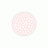
Here are some drawings of wire cross sections inside of a toroid window. One with 65 turns and one with a lot more.
If the window area was rectangular then we would have the problem of fitting small circles inside of a much larger rectangle instead of fitting small circles inside a larger circle, that's all.
The drawings are more or less like the result from a human winding the turns, with no tape.
Take note (especially the first drawing) that there is some area in the window which does not contain any part of the wire. That's because the wire does not fit exactly into the window (only one turn as big as the window would be able to do that).
Also take note that the area of the wire really includes the enamel insulation.
 

Attachments

  • NEWBIM0065.gif
    NEWBIM0065.gif
    10 KB · Views: 161
  • NEWBIM17373.gif
    NEWBIM17373.gif
    66.3 KB · Views: 165
Last edited:
Good info. Thanks. I'm gonna book mark that since i don't have a book.

Regarding the window, I guess I had always in the back of my mind decided I would only neatly wind a single layer only which was why the window area thign never occured to me. About the Gauss limits you are recommending, a rule of thumb is to stay less than around 5-10% of the core material's saturation flux density? You're just talking about staying well away from the knee region right? They actually have pretty complete data so it's kind of nice to know exactly how the core saturates. Maybe I'm overlooking something but wouldn't it be okay to operate the maximum at around 50%?

It's gonna be a MPP or Sendust core which saturates at 8000G or 10,000G. THere's still a crapload of room with just 8 turns on a core that size so I could easily fit in more turns which would bring down the flux density quite a bit.

Ahhh...tape...that's how you neatly wind layers on top of each other.
 

Attachments

  • MPP.pdf
    723.5 KB · Views: 586
  • Sendust.pdf
    367.1 KB · Views: 397
Last edited:
Hi.
The way I charge my Li-ion multicell battery pack is using a single voltage supply about 4.3V times number of cells in series, with zener diodes in parallel to each cell, that can be switched on and off circuit by a 2 pin header and jumper. It may not be the best of the solutions but works very well for me. While charging, jumpers are installed. When charging ends jumper are pulled out.
(As you want less complication)

+--------------cell1--------A--------cell2--------B-------cell3----------C-----....
+-------•_•---zener1-------A--•_•---zener2------B---•_•---zener3-----C-----.... <---- shown in not charging open circuit.

The zeners I use are 1W 3.9V, cannot remember the numbering now, and when cells are about 4.1V, zeners get slightly warm telling me they are done, confirmed by measuring voltages.
The jumpers could be replaced by a multiple contact relay, energized only when charging to place all the zeners in circuit.
 
Last edited:
Good info. Thanks. I'm gonna book mark that since i don't have a book.

Regarding the window, I guess I had always in the back of my mind decided I would only neatly wind a single layer only which was why the window area thign never occured to me. About the Gauss limits you are recommending, a rule of thumb is to stay less than around 5-10% of the core material's saturation flux density? You're just talking about staying well away from the knee region right? They actually have pretty complete data so it's kind of nice to know exactly how the core saturates. Maybe I'm overlooking something but wouldn't it be okay to operate the maximum at around 50%?

It's gonna be a MPP or Sendust core which saturates at 8000G or 10,000G. THere's still a crapload of room with just 8 turns on a core that size so I could easily fit in more turns which would bring down the flux density quite a bit.

Ahhh...tape...that's how you neatly wind layers on top of each other.


Hi again,


Yes just because the core can handle 10kG flux density doesnt mean we can operate it at that level at 100kHz. As the frequency goes up, the core heating goes up, but bringing down the flux density decreases the core heating. Thus, the level of B chosen for the design is more a matter of frequency. The target power density we are after is 100mw/cm^3, and at 100kHz we get about that when the B level is around 500. Check out those core loss curves in the links you provided. If we went with 5000 (50% of 10kG) instead of 500 the core heating would make it Earth's second sun :)
Looks like they provide some pretty good data for those cores, thanks for the links.

P.S.
I just took a look at the Sendust core data and it looks like 300G may be better then 500. For the MPP type 400G would be ok instead of 500, although you probably want to check again with the actual material you intend to purchase.
 
Last edited:
All problems can be solved with more turns? lol. I just kind of picked 8 out of thin air originally because its the minimum to be evenly distributed around the ring. Doubling that to 16 isn't that many I don't think and brings B down a lot. I'm still kind of just picking my turns number based on flux density and even distribution around the core rather than inductance. I don't see how inductance plays a role in this case since I'm not using inductive spiking to boost the voltage. (Obviously, let me know if I'm wrong but it just seems like inductance hasn't been talked about at all and other things take precedence).

After learning the labellings behind Litz wire it also seems that Bytemark also carries one that actually has my required current levels and frequencies. At about $20 per 30 feet which I'll probably pay for just to make my life a bit easier and reduce my chances of messing up.

I sort of get it now looking at some of the cores of the same permeability. Some are larger, but with less cross sectional area but have a massively larger window so you can stick more turns into them. And they cost more as a result.
 
Last edited:
Hi again,


The more turns the better for the core flux, but the less turns the better for the wire losses (DC resistance as well as AC resistance). Every time you double the wire length, you double the wire resistances and bring the wire losses up somewhat but the core losses will go down. The alternative is to use a bigger core, which introduces more volume and more losses that way, so it's a tradeoff.

Hopefully not to sound like a wise guy, but we have been talking about inductance all along, just not in the form you are probably used to hearing about (an actual inductor value). B is the induction and that is the Faraday equation and that takes care of everything in a nutshell.
The mutual inductance however is something we havent talked about yet but it probably doesnt matter that much because we dont have a whole lot of control over this anyway. We hope we get as near to 1:1 coupling as possible, but we live with what we actually get.

There could be some inductive spiking now that you mention it, and in fact there almost definitely will be at least some. This happens when both transistor turn off for a short time (dead time). The spike that occurs should be short but the exact height is difficult to predict. A pair of snubbers using a resistor and capacitor each will probably take care of it with minimal losses. This is something that absolutely has to be tested for using the scope.

Oh so you are thinking of going with some Litz wire? How many strands for 14 AWG ?

Sometimes to get the core size the quantity WaAc is calculated, which leads to a core with a given Window area times Core area. It's not really as intuitive though and you still have to enter a fudge factor to leave some extra space in the window.

I think what we could do if you like is we could probably come up with a functional method based on the information presented in this thread. That would be interesting too i think. This could have wire size built in too i think.
 
Last edited:
THe litz wire that is available in low quantities is more akin to 18AWG than 14AWG. It's 175 strands of 40AWG wire. The 40AWG seems to be recommended for 100kHz-200kHz or 200-400kHz depending on where you look. Skin depth calculator puts it at around 100% depth and regular 40AWG wire has a current rating of 90mA. So "supposedly" 175 strands is a rating of 15.75A, but probably need de-rating there since it does count as a bundle.

My original goal was the following:
1. independent cell charging
2. maximum of 3C rate for a 5Ah cell
3. 6V input capable

Spec #2 and #3 probably aren't achievable together due to the Litz wire gauge available. But spec 3 isn't important anyways because most of the time the supply voltage will be at least 12V halving the transformer current requirements (and 24V on occasion). As long as the buck stage can handle the 15A for charging 5Ah at 3C, it'll be fine. Even the 3C 5Ah rate is greatly oversized for my current charging needs. It's more of a futureproof thing. I'm going to be overbuilding the push-pull circuitry and buck circuitry anyways. It's easy enough to swap the toroid core and/or wiring to increase things in the future.

Yeah I'm aware of the need for snubbers. I was talking more about inductance required to perform the application rather than parasitics. But I didn't see how that played into this if I just needed it to move a signal from one winding to another. Like I know now how to pick the core so it doesn't saturate and use the number of windings to get the ratio and flux density that I want, but in the back of my mind I still know there's inductance in the transformer that has a necessary value in certain applications but that I didn't seem to need it. Sort of like an overspecified problem.
 
Last edited:
Hi again,


Can you get anything bigger?

Oh wait a minute, 175 strands of #40 comes out to about a #18 AWG, which is close to #17.
Two layers of N turns for the secondary.

BTW, i dont know how much you care about the effciency, but a center tapped secondary has the advantage of requiring only 2 diodes, where only 1 diode conducts at any given time. In contrast, a bridge has 2 diodes conducting which lowers the efficiency when dealing with lower voltage outputs like 6v.

If you operate at 12v input, that's roughly 1/3 to 1/2 the input and output current at 4.2 volts.
 
Last edited:
Are you absolutely certain about that? How did you come up with that number? Because the 40AWG wire is .00501mm^2. 175 times that is 0.87675mm^2 which is somewhere in between 17 and 18 AWG. I also requested a quote from the manufacturer and specified 40AWG strands with 16-18AWG equivalent and they sent back the 170 strands as part of the spool specification.

EDIT: Nvm. You recalculated.

I mainly care about efficiency in the sense that my AC-DC power supply is limited in power (boo for physical limits!), and there's a maximum number of cells I want to be able to charge (10 or 12). Though I am going to be using under 6 on a much more frequenct basis.

Pertaining to the diodes. My original train of thought has always been two diodes with the center-tapped transformer if you can get your hands on one. But last night I was sitting there thinking it might be better to use 4 diodes because now I'm actually the one doing the winding and it is easier and cleaner to wind a secondary with no center tap. It also makes better use of the copper. The extra voltage drop would be a big deal at 6V since the buck wouldn't be able to run anymore with the voltage drops. but that's kind of solved at 8V or 9V. And obviously, not as much at 12V or 24V. Right now, I have no preference either way because that 6V input goal is more of a preference thing really but in practice probably not going to be used much. It might come down to a matter of seeing how much room is on the toroid after I've wound the primary. Of course...litz wire costs money too for that extra winding that's only used half the time.
 
Last edited:
I also found Ebay Litz wire. Same 17-18AWG size, but the strands are smaller to accomodate for frequencies more around 800kHz-1.3ishMHz. I'm pretty sure that's past the point where the increase in DC resistance starts to outweight the resistance caused by the skin effect for my 100kHz frequency.

Litz wire 660/46 for crystal radio coil Loop anten 60' on eBay.ca (item 160428065987 end time 25-Jun-10 18:53:07 EDT)

All the prices of the Litz wre everywhere seem almost identical to manufacture direct. The only difference is the minimum order quantity (which is still suprisingly low from the manufacturer.)
 
<snip>
It might come down to a matter of seeing how much room is on the toroid after I've wound the primary. Of course...litz wire costs money too for that extra winding that's only used half the time.


I thought you wanted more output current so you were going to double the layer for the secondary, that would make two windings bifilar of Litz wire anyway, and with a center tap the wire only has to be on half the time so that's two lengths of Litz wire too.

In any case, if you intend to ever work at 6v input you may want to use more secondary turns than a perfect 1:1 so that you can ensure the output is high enough.
 
Oh, if I doubled up the winding I'd just make it centertapped yeah. But yeah...since the primary already has two windings because of the center-tapped, having a single non-center-tapped winding on the secondary might make full use of the secondary winding but then half of the current capability of the primary goes to waste. Or, make a center-tapped secondary with only 50% utilization but it makes use of the full current capability of the primary.
 
Last edited:
Hmm, it looks like the transformer is not the current bottleneck after all. The buck charger is also much more difficult to design than I originally thought. I don't understand current mode control so I have to use a battery charger IC, but they have very limited gate drive capability (something I could eaisly solve if I was building the circuit discretely). Then again, I am not used to build immobile circuits so I just need to get used to the ability to actually add active cooling and large heatsinks.

A big problem is the high frequency that the charger ICs run at to minimize inductor size. Right now, inductor size is far easier for me to deal with than heat dissipation due to FET switching. But no dice.
 
The buck converter is one of the simplest DC-DC converters to design…

Take a look at:

**broken link removed**
 
Hi again,


If you want to charge an Li-ion cell then you need voltage mode with current mode control, and most buck converters are built using voltage control. You just have to add current control. Current control is almost like voltage control only instead of measuring voltage and feeding that back the current is measured and that is fed back. You also have to logically 'OR' the two so that either one can have control, depending on the other. This is usually forced through design or it comes about as part of the design anyway. Usually some kind of sense resistor is used to measure the current.

BTW, the inductance question you were asking about before...

If we look at a BH curve for a core we note that for a given B we get a given H (more or less) and for a give H we get a given B, so B and H are uniquely linked so that if we know one we know the other. That means we only have to know one.
Now taking the equation for B and the equation for H and recognizing that B=ur*H, we can equate the two and eliminate B. After a few substitutions including L=E/(w*I) we end up with the equation for inductance (approximately) in the form L=f(x), which tells us the inductance of the primary.
The formula for the inductance is:
L=Ac*Np^2*u0*ur/c
where
L is the inductance of the primary in Henries
Ac is the area of the core in cm^2
u0 is the magnetic space constant, adjusted to Henries/cm
ur is the relative permeability of the core
c is the mean magnetic path of the core

In this way you can calculate the inductance of the primary if you like, just to see what you get or whatever you want to do with it.
 
Last edited:
Hi indulis. I know how to select the hardware for a buck regulator. I am talking about the control theory behind the buck converter. The current and voltage mode control, the frequency/ramp compensation, and dominant poles and stuff like that. The stuff that tends to be taken cared of if you just use an IC (which is becoming a limiting factor since they have limited gate drive and frequencies that are too high for the power dissipations I require.

Whenever I can actually find something that talks about it, it's really difficult to muddle through.
 
Last edited:
The stuff that tends to be taken cared of if you just use an IC which is becoming a limiting factor since they have limited gate drive and frequencies that are too high for the power dissipations I require.

Sorry... I lost you here. PWM's nowadays have a 1A or 2A of dive current. How can the frequency be too high? You get to use a smaller output inductor and capacitors. High is also a relative term... 100KHz is not "high" and is fact low in relation to what you'll find today. 300-400KHz is common in multi phase VRM's and some of the lower power units with fixed frequency PWM's run in the 600KHz area.

Stay away from voltage mode control if you can... it will have the dreaded right-half-plane zero, which is a pain to deal with. In current mode control the output inductor looks like a current source and the double pole formed by the LC goes away. The dominant pole is from the output C and load R. The zero is from the ouput C and it's ESR. BTW- in current mode there are 2 loops... an "outer" voltage loop and a "inner" current loop.

Marty Brown from Motorola wrote a book that has a simple to understand explanation of the transfer functions of different topologies, control methods and loop compensation methods (type 1, 2 and 3 error amp configurations)

Amazon.com: Power Supply Cookbook (EDN Series for Design Engineers) (9780750670104): Marty…
 
Last edited:
I'm finding the primary problem is in the switching transistors. In the handful of transistors I've looked at so far, the frequency is too higih and drive current too low causing the transistors to become excessively hot. This is not a mobile application so size of the inductors doesn't really matter. The charger ICs I was looking at have 0.3A to 1A of current (usually on the lower end), but run at frequencies that are 5-10x what I was expecting for the current levels I'm using. I'm still hunting around for transistors however. Perhaps one reason is that the charger ICs I'm looking at seem to be targetted to a maximum charge current of 10A and I want higher than that. I found a whitepaper that was talking about the requirements of buck converters being used to charge batteries and there's a bunch of complications that might come up. Some of which I have no control over since it's hidden inside the chip so I can't use a regular buck converter.

Yeah, I probably should get a book. It's funny that the thing I work most with is power stuff, but dont have a textbook. I have a bunch of communication textbooks, and some control textbooks, but no power books at all. Probably should use those control books to brush up on my control theory too...that stuff was a doozy when I took it lol.
 
Last edited:
Status
Not open for further replies.

Latest threads

New Articles From Microcontroller Tips

Back
Top