Continue to Site

Welcome to our site!

Electro Tech is an online community (with over 170,000 members) who enjoy talking about and building electronic circuits, projects and gadgets. To participate you need to register. Registration is free. Click here to register now.

  • Welcome to our site! Electro Tech is an online community (with over 170,000 members) who enjoy talking about and building electronic circuits, projects and gadgets. To participate you need to register. Registration is free. Click here to register now.

Winding a transformer?

Status
Not open for further replies.

dknguyen

Well-Known Member
Most Helpful Member
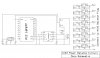
Hello, I'm toying with the idea of a multi-channel battery charger. But a key component is a swtching transformer to provide isolate voltages to power the charging circuits for each channel. So I need a toroidal transformer with an input center tap (for push-pull) and eight 1:1 output taps that can work at at least 100kHz and support 10A per output winding (which would mean an 80A input winding I guess).

My design goal is for a charger than can chanrge a multi-cell pack from a 6V-24V source hence the 1:1 transformer ratio and the high current. In reality the current is usually going to be less by half as much or more. Each output winding is going to have a buck regulator that requires enough input voltage to run itself and produce 4.2V for the purpose of charging the battery cell. So the voltage on the output windings just has to be ~6V to power the buck. Being a 1:1 ratio, and the fact that usually a 12V supply or higher is available, the actual current in the transformer can easily be at least half as much, with the buck regulator stepping down the voltage and stepping up the current to required charging levels.

I'm having trouble finding the equations to figure out the core size to select and sources for said cores. I also don't have a feel for the numbers or materials, so if such a large transformer for such a high frequency is not possible, please let me know. Because from where I'm sitting, now that I actually typed out my requirements, I suspect it might be too large at too high a frequency.
 
Last edited:
I found a possible source:
Sendust Toroidal Cores for Chokes and Inductors : CWS ByteMark, largest supplier of toroids, ferrite cores, iron powder cores, MPP cores and RF cores

and this datasheet:
https://www.electro-tech-online.com/custompdfs/2010/06/OD20777.pdf

Is it really that simple? Just use the NI equation and use the graph to figure out the frequency? I seem to remember having to calculate flux density and stuff like that.

I'm also unsure as to whether you're supposed to wind interleaved windings or not. I read that it helps with leakage inductance but increases capacitive coupling. Or just wind each winding continuously side by side with other windings on the toroid? THere's also issues of single or multi-layer (out of curiosity) since single layer is so much faster and this is heavy gauge wire.
 
Last edited:
Sounds like you are still within the working limits of a rewound HF transformer from a bigger computer power supply to me. 6 volts at 80 amps is 480 watts output and I have seen a number of computer power supplies pushing wattages far higher than that on the output side now.

Also if all the output voltages need to be the same why not just use one for the referance feedback point and have the switching system automatically regulate each of them to the same voltage all together?
 
When you say output voltage, do you mean the actual charging output voltage on each channel? Or the output voltage of the winding? I didn't mean to imply any of those voltages had to be precisely the same...not even similar. As long the buck regulator on each channel can handle it to produce 1V-4.2V for charging. As for the actual output voltage of each channel buck, it's not supposed to be the same. THey are charging the cells independently.

Even though it was due to misinterpretation, I'm still scratching my head as to what you mean by your last sentence. Are you talking about an alternative to not using at transformer? Or having all the buck regulators match voltages? Or are you talking about using the transformer push-pull circuit to regulate the winding output voltage (I don't see how that's possible since all windings are ratiometrically linked to each other).
 
Last edited:
Hi.
Am more familiar with Telecom and Datacomm Single and Dual Output DC/DC Converters, Telecom Power Solutions | SynQor ; but there is hundreds of manufacturers, adjustable models, duals that could be a better approach than imprecise windings for an accurate need charging Li-ions.
Sharing the same raw DC source, provide isolated multiple outputs one for each cell.

Four DC-DC doubles or eight singles are surprisingly small for 10A and available at DigiKey, Mouser...
 
I thought about that when running into the problem of high current switching transformers (single and multi-tap), but after looking at 50W isolated converters, but from what I've seen they're all about $100 each.
 
Last edited:
Hi there,


Im not sure if i understand you right, you are saying you want to build a charger that can charge on 8 channels and puts out 10 amps each, and the nominal voltage will be around 4.2 volts right, and you want them all isolated?

My first question is, why isolated? Batteries dont have to be isolated to be charged. Heck, you probably dont even need a transformer, just 8 buck regulators with added current regulation. Buck should work out pretty well at 6 to 24 volts input and 4.2v out. We could get this working pretty quick like one day.

Second, you dont want to use 'heavy' wire anyway, you want to use multi strand at 100kHz to reduce skin effect losses, if in fact you do go with one or more transformer(s).

Third, did you consider making (simple) 8 individual chargers, if you do have to isolate, that way you can make one, get it working perfect, then simply repeat 7 more times. Several transformers or no transformers, it's a very sane way to build something you dont do every day.
 
The isolation is so that each cell in a series pack can be charged individually. The goal is to get rid of the standard runabout method of charging the battery normally and then dissipating charge from cells that are too high. It slows down the charge time (sometimes making the overall charge time actually take longer at faster charge rates because the cells need more balancing), and there is debate of the ineffectiveness of dissipative balancers due to the flat discharge curve of some types of cells now allowing the cell voltage to be used as an accurate indicator (and instead requiring a current method which can only be done during the charge top-off).

I did consider eight isolated chargers each containing it's own isolation supply and buck switcher. The main reason I'd prefer a a single large multi-output winding transformer is to reduce the parts count. Eight isolation supplies seemed like quite a few parts that could be replaced with fewer number of parts. Individual isolation supplies does have the advantage of modularity though...no inherent limit on the number of cells, just add on another charger. And it would make frequency issues less of a crapshoot. Of course, going the individual transformer route, it might be possible to simplify things by replacing the isolation supply and buck charger in each channel with just a flyback charger (though getting voltage and current feedback is the main difficulty there).
 
Last edited:
A second thing...somebody built something on a smaller scale and ran into an interesting problem I can't explain.

A123 Balancer Project - WattFlyer RC Electric Flight Forums - Discuss radio control eflight
That was strange. If you run the multiple channel charger into a circuit simulator program, the highest voltage cell will be charged at the proper rate. The next one down gets the top cell and its own cell, the third one down gets higher charge rates. And so on.

By the time you get to the bottom cell, the charge rate was over 1/2 amp, and overloaded the 3.6 volt regulators. It just didn't work.

The same thing would happen if you took six individual power supplies with 3.6 Volt DC outputs, and connected them all to each cell of the 6S battery pack. The bottom one will get far to much charging current. That's what the circuit simulator showed me, and that's exactly what I got in real life.
 

Attachments

  • KyleServiceTech A123 Balancer.jpg
    KyleServiceTech A123 Balancer.jpg
    96.8 KB · Views: 210
Last edited:
The isolation is so that each cell in a series pack can be charged individually. The goal is to get rid of the standard runabout method of charging the battery normally and then dissipating charge from cells that are too high. It slows down the charge time (sometimes making the overall charge time actually take longer at faster charge rates because the cells need more balancing), and there is debate of the ineffectiveness of dissipative balancers due to the flat discharge curve of some types of cells now allowing the cell voltage to be used as an accurate indicator (and instead requiring a current method which can only be done during the charge top-off).

I did consider eight isolated chargers each containing it's own isolation supply and buck switcher. The main reason I'd prefer a a single large multi-output winding transformer is to reduce the parts count. Eight isolation supplies seemed like quite a few parts that could be replaced with fewer number of parts. Individual isolation supplies does have the advantage of modularity though...no inherent limit on the number of cells, just add on another charger. And it would make frequency issues less of a crapshoot. Of course, going the individual transformer route, it might be possible to simplify things by replacing the isolation supply and buck charger in each channel with just a flyback charger (though getting voltage and current feedback is the main difficulty there).


Hi again,


Ok so i see you have a fair reason for wanting to go with isolated channels, that's fine.
Now left is the decision to go with one big transformer or eight smaller ones.

One thing i dont see here though is someone winding a transformer (possibly a toroid core) with NINE (yes, count 'em, 9) windings using multi strand Litz wire or at least bifilar that is not used to winding transformers at all. It would be a LOT simpler and easier to wind one transformer with one primary and one secondary and get that working properly before proceeding to the others.
You also should keep in mind that outputs for something like this often use center tapped windings to allow the use of only two Schottky diodes instead of four. The primary is often center tapped too to allow the use of only two driver transistors instead of an H bridge that requires four.
Still, it's up to you of course.

In any case, the buck is a very stable regulator compared to other types so that's not a bad choice for regulating. The transformer would supply the square wave, then rectified, filtered, supplied to the buck regulator, and that's about it.
If you want to go with primary regulation then it gets a bit more complicated because you've got to figure out how to get the feedback to the regulator while it is still isolated, and still have it be fairly accurate.

To design the transformer you would normally look at the curves for the materials and try to find one that has a lower watts loss vs frequency. 100kHz isnt that bad i guess, 50kHz even better maybe. The Faraday equation comes into play in calculating the primary turns. There are procedures that are outlined on sites like the Magnetics Inc site in their handbooks.

LATER:
I took a look at that link and found that those toroid cores would probably work at around 500 Gauss at 100kHz.
Might push the High Flux version up to 700 or 1000.
Those cores might be easier to get than the Magnetics Inc cores unless we could find a distributor that sells low quantities (R material looks promising).
10 years ago Magnetics Inc min order was about 200 dollars USD. Their design info is still useful though.

Another thing in favor of using one core per channel:
If we have to go through any experimental iterations regarding the number of turns it will be a heck of a lot easier to change two windings instead of nine, and once it is right on one core the other seven will work without any tries.
 
Last edited:
Yeah the flyback charging method doesn't seem worth it due to the hassle of the feedback. Lots of bits and pieces everywhere.

Yeah I was sitting there staring at at the wall thinking about how much more room it would take to wind 9 center-tapped winding (really, 18 coils lol) on one toroid to accomodate the push pull circuit and allow full-wave rectification with 2 diodes. THat seemed a bit unreasonable so I thought it might be easier to make the output windings non-single tapped but have 4 with reverse polarity to the other four. That might help reduce the current in the input winding but I don't think it does really...the peak currents are still pretty bad. It also doesn't solve the frequency problem with heavy gauge wire (which is also a pain to find from the same distributor as cores to reduce shippign costs). And of course no modularity. This project is kind of here because it's something I want, but doesn't necessarily require processing power that my two main projects require and I'm sort of dodging having to learn FPGA System Planner and AutoCAD right now lol. Individual transformers is a bonus there too since I can start small and stay small if I wish. I definately don't want to use 4 rectification diodes or an H-bridge drive.

Interesting link RC...shuttling around current between cells to balance instead of charging each one individually.
 
Last edited:
Yeah the flyback charging method doesn't seem worth it due to the hassle of the feedback. Lots of bits and pieces everywhere.

Yeah I was sitting there staring at at the wall thinking about how much more room it would take to wind 9 center-tapped winding (really, 18 coils lol) on one toroid to accomodate the push pull circuit and allow full-wave rectification with 2 diodes. THat seemed a bit unreasonable so I thought it might be easier to make the output windings non-single tapped but have 4 with reverse polarity to the other four. That might help reduce the current in the input winding but I don't think it does really...the peak currents are still pretty bad. It also doesn't solve the frequency problem with heavy gauge wire (which is also a pain to find from the same distributor as cores to reduce shippign costs). And of course no modularity. This project is kind of here because it's something I want, but doesn't necessarily require processing power that my two main projects require and I'm sort of dodging having to learn some of the FPGA layout software right now lol. Individual transformers is a bonus there too since I can start small and stay small if I wish.

Interesting link RC...shuttling around current between cells to balance instead of charging each one individually.

I still don't know how to select the core size and frequency though (my knowledge of transformers is rather weak). The closest I've come by is to calculate NI with a number of turns I like and the current I require, and then pick a transformer where that number is more towards the high end of the Al vs N curve, and locking into a frequency of 100kHz since that's what the curve given is for. I'm not even sure if inductance is important...this is mainly an isolation application and not a "energy storage and sparking/flyback application" so my my lacking intuition here tells me inductance isn't particularily important.
 
Last edited:
Hi again,


The design and core selection process could go something like this (there are other ways too)...


To start you would figure out the max primary current and that would tell you the primary wire size if it was a single winding of one wire. Since it would be better to use two strands, the required wire for a single winding would have half the area. Now if it is to be center tapped (push pull input) you can reduce the wire by one half again. Now you know the wire size for the primary.
The secondary is basically the same, and then you have the secondary wire size.

Now having both sizes (and of course the final topology to be used) using the equation with N=primary turns:
B=E*10^8/(4*FAN)

where B is the max allowable for the material of the core for a given max power density,
E is the peak voltage,
F is the frequency,
A is the core cross sectional area in square cm (can start with 1 cm^2)
N is the number of turns (of the primary)

Now knowing the turns of the primary, calculate the turns of the secondary with say 10 percent margin.

Next, look up the actual wire size with heavy enamel.

Next, compute the total window area by using the geometry of small circles fitting inside of a large circle (all wire diameters must fit inside the window with say 50 percent margin). You can probably estimate this as A1/(N*A2)=0.5 roughly.

Now knowing the window area, find some cores and note their cross sectional area.

Stick the real cross section into the equation above and compute again, etc., etc.

Eventually you come up with a core with a large enough window and enough cross sectional area.

For B for most cores at 100kHz a max of 500 would probably be a good target level for the induction to keep the core power equal to or lower than 100 mw/cm^3 which is a good target for 40 deg C or less temperature rise.

Real simple example:
E=24v
F=100000Hz
A=1 sq cm
N=12 turns
B=E*10^8/(4*FAN)=500 Gauss

For a single primary winding (not push pull).
Lets say 10 amps primary, this would mean #14 gauge wire, divided by 2 would be 3 sizes down or #17 wire which
has a diameter of 0.0453, and the area of that wire is 0.001611708 .
With a window diameter of 1/2 inch that would be an area of about 0.196, divided by 2 that's 0.098, and that divided by the wire area gives us 61 turns, so 61 turns should fit. We need 12 plus another 12 for the secondary (10 amps) so 24 turns would leave a lot of area left over so we could try a smaller core.

For the driver for a push pull circuit we would try to make the two transistor drivers as close to the same as possible to minimize dc current ratcheting in the primary.

Part of the testing would include looking at the primary current to look for current spikes which indicate primary saturation.
 
Last edited:
What do you mean it's better to use two strands?

And for center taps where does the center tap actually come from? Is that centertap just the ends of two series connected windings connected together?

EDIT: Do you mean bifibilar winding?
 
Last edited:
Hello again,

Two strands meaning two wires instead of one. It's a simple concept really, if you compute the size required for a single strand then you just divide the area by 2 to get the required area of the two strands (looking up the new wire size will mean going 'down' 3 wire gauges).
If your normal wire looks like this:
-----------------------------------------

then your double strand looks like this:
-----------------------------------------
-----------------------------------------

except the double strand has 1/2 the area for each wire. You basically cut two wires, hold them side by side, leave enough extra for lead length, start winding but winding with the two wires instead of one. After you are done you have a bifilar winding. Both wires are used as one wire because you connect them at the ends. Of course the more strands the better, but when you get past two or three strands it gets hard to wind by hand so you can use Litz wire instead if you like, but it may be expensive, and you probably dont need top efficiency with this design anyway.

The center tap for a single strand winding is done the same way a bifilar winding is done, taking two in hand at a time, leaving room for lead length, but when you are done instead of connecting the ends as with a bifilar you take one end from each side (from the separate strands) and connect them together...that's the center tap. It's somewhat important to do it this way so that both windings are the very same length and are pretty much in the same position magnetically.

Of course for a center tap that is also to be done bifilar, you would take 4 wires in hand (two pairs) and wind as if you only had two wires in hand.

Recap:


Bifilar (A connects to A, B to B):

A-------------------------------------B

A-------------------------------------B

This still only gives us two terminals.


Center tap (same except one each from opposite ends are joined):

A-------------------------------------B

B-------------------------------------A

Center tap can be either both A's or both B's. That gives you three terminals.


Of course if you wind for a center tap AND bifilar, you would have double wires for each wire shown for the center tap above.

https://en.wikipedia.org/wiki/Bifilar_coil
 
Last edited:
So it's soley for frequency purposes? Sort of like how in motors they wind everything with very thing solid wire and then run the wires out and twist them into 3-bundles to form 3 regular looking pieces of wire?

Efficiency isn't my top concern here. I'm more worried about overheating due to saturation or skin effects. Sendust cores are so cheap compared to those PMM cores. From staring at material spec sheets it seems they're fairly similar...nowhere near worth the 400% difference in price for my application. Or get 4x as large lol, but with 8 transformers...that's pretty big heh. I'm more likely to be conservative with my core selection and just wind a 1:1 with a comfortable number of turns to be mechanically stable and spread itself evenly amongst the toroid. I'm not sure how important inductance is in this case though.

I obviously have something wrong with my conceptualization of magnetic cores since I would have though more turns would increase the flux density but apparently it decreases it. Hmm. I should realy get a book on transformers and switching power designs. They're just so expensive lol.
 
Last edited:
What I was referring to earlier is how many multi voltage power supplies work. They use one of the secondary windings as the master referance point for the feedback circuit and all others are proportional to that reference winding by turns ratio.

I have taken apart numerous computer power supplies and many industrial aplication power supplies where only one or two outputs have a direct feedback to the switching circuits in order to maintain the correct operating voltages for all the outputs. Most computer power supplies use only the 5 volt and 3.3 volt outputs for the actual referance points for output voltage regulation. The negative outputs and the 12 volt outputs do not have feedback to the switching circuits but rather use the pull down effect the transformer over the referencing outputs to regulate the overall system in order to maintain the correct output voltage.

Indirectly they are all still regulated albeit not as precisely as the outputs that feedback directly to the switching control system but still close enough to keep the systems overall regulation per individual output section regulated well enough to not cause problems.

In your case the multiple secondaries would all be wound the same but only one or two would have a direct feedback link to the switching circuits in order to maintain the correct output voltages for all of the secondary outputs.

Its just one way of getting reasonable voltage regulation over multiple output circuits without an overly complicated secondary control system or feedback loop circuit needing to sample every individual output.
 
Last edited:
So it's soley for frequency purposes? Sort of like how in motors they wind everything with very thing solid wire and then run the wires out and twist them into 3-bundles to form 3 regular looking pieces of wire?

Efficiency isn't my top concern here. I'm more worried about overheating due to saturation or skin effects. Sendust cores are so cheap compared to those PMM cores. From staring at material spec sheets it seems they're fairly similar...nowhere near worth the 400% difference in price for my application. Or get 4x as large lol, but with 8 transformers...that's pretty big heh. I'm more likely to be conservative with my core selection and just wind a 1:1 with a comfortable number of turns to be mechanically stable and spread itself evenly amongst the toroid. I'm not sure how important inductance is in this case though.

I obviously have something wrong with my conceptualization of magnetic cores since I would have though more turns would increase the flux density but apparently it decreases it. Hmm. I should realy get a book on transformers and switching power designs. They're just so expensive lol.

Hello again,


tcmtech:
Nice of you to join in the discussion :)
The computer power supplies do not demand good precision on regulation, so one feedback for several voltages is usually ok. For this application however (i believe Li-ion cells will be involved) we want 1 percent or better on each output. Most computer supplies are 5 percent or worse.


dk:
Yes, using more than one strand is for frequency, the higher you go the more strands the better. Litz wire is often used for this, but i really think we can get away with 2 strands here. It may even be possible to get away with one strand, and since we will probably be dealing with a low number of turns you may want to try this first and see if you like the efficiency.

As far as overheating, that's why we want to stay low on the induction, 500 or less.

A larger core is ok, as long as you keep in mind that the power density will be about the same, so the more material the more loss.
I think you will do ok with a 50 percent overkill on window area. That leaves room to breath. If you test and feel that the power loss is too great (i doubt this though) then go to a smaller core.

Inductance itself will be ok as long as we follow the equation i gave earlier. That's sometimes called the "Transformer Equation" and varies a bit depending on wave shape.

You are not entirely wrong however regarding the flux vs turns. For the transformer basic operation the more turns the better (from the perspective of the core area) for the ac part, but for any dc current that may be present you are 100 percent correct in that the more turns the worse it is. That's why we try to keep the drivers matched and hopefully have enough overhead to absorb any mismatch. Gapped cores are often used to help with the dc problem so hopefully you wont have to worry about that.
The TI site has some pretty good information on transformers for switchers i think, so probably dont have to buy any books yet :)

I think what i would do at this point is do a few calculations, buy a core, buy some wire, and do some testing. Testing a square wave drive into the primary with a resistive load of appropriate value would paint a very clear picture of what it can do. Buy one core one size, then another core the next size up perhaps, or even another core one size down, just for experimentation. That's the fun part of it :)
Note that we dont even need any regulating circuitry yet to test the core and windings.
 
Last edited:
Output regulation of the transformers is not an issue since it has to be followed by a buck converter which is serving as the CC-CV charger as each individual cell is assumed to be at different points in the charging cycle.

Yeah, the main reasons I wanted to go with a push-pull circuit were the two low-sided switches (yyyyaaayyyyy!!! so easy to work with!) and the zero DC to not saturate the transformer over switching cycles. Since I only care about producing an isolated voltage and don't actually care about regulation, I'm just going to run at 50% symmetrical duty cycle.

As far as this core testing is concerned, its low risk. Usually its several hundred dollar PCB that needs all the components mounted on it to see if it will work which costs even more money and time, and the nothing can be resused if it doesn't. Cores that are usually about $5-$10 (and maxing out at $30 each) that can be rewound if things don't work out...walk in the park as long as something isn't terribly wrong lol.
 
Last edited:
Status
Not open for further replies.

New Articles From Microcontroller Tips

Back
Top