Continue to Site

Welcome to our site!

Electro Tech is an online community (with over 170,000 members) who enjoy talking about and building electronic circuits, projects and gadgets. To participate you need to register. Registration is free. Click here to register now.

  • Welcome to our site! Electro Tech is an online community (with over 170,000 members) who enjoy talking about and building electronic circuits, projects and gadgets. To participate you need to register. Registration is free. Click here to register now.

will this circuit work?

Status
Not open for further replies.

strokedmaro

New Member
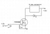
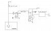
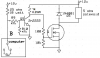
This is another transmission project Im working on. The computer on the schematic normally operates a solenoid by applying a ground. This project however requires a different solenoid to operate. The original solenoid is about 22 ohms and the new one is only about 5 ohms. Ive replaced the original solenoid with a 25 ohm, 10 watt resistor so the computer will "see" the correct value and not throw a code. I kind of figured out that the paralleling of the 25 ohm resistor and the 220 ohm one work out to be about 22.44 ohms which the computer will accept as "good." This would also allow Q7 to operate the new solenoid for the project. Will this circuit operate reliably or at all? Thanks

P.S. The arrow next to the computer is where I would splice the project in at
 

Attachments

  • circuit.JPG
    circuit.JPG
    54.1 KB · Views: 278
Last edited:
As written, no, this doesn't work. If you showed the other connection to the solenoid, it might.

The original solenoid is about 22 ohms and the new one is only about 5 ohms. Ive replaced the original solenoid with a 25 ohm, 10 watt resistor so the computer will "see" the correct value
This is unlikely to work because the new solenoid needs enough current to operate. It draws 2.4A at 12V but with the resistor, it will see 400mA. The old one only needed 540 mA and your circuit was probably sized to deliver that current. While your circuit won't "throw a code" (what ever that means), you won't be able to deliver enough current to the solenoid (technically, draw enough current from) so get rid of the resistor. Then, you should look at the transistor specs and see if it can handle the current (Ic). If not, you will need to upsize the transistor and make sure that it's getting enough base current times its Hfe to satisfy the new solenoid's requirement. I'd try to find a closer match on the solenoid.
 
Last edited:
As written, no, this doesn't work. If you showed the other connection to the solenoid, it might.

This is unlikely to work because the new solenoid needs enough current to operate. It draws 2.4A at 12V but with the resistor, it will see 400mA. The old one only needed 540 mA and your circuit was probably sized to deliver that current. While your circuit won't "throw a code" (what ever that means), you won't be able to deliver enough current to the solenoid (technically, draw enough current from) so get rid of the resistor. Then, you should look at the transistor specs and see if it can handle the current (Ic). If not, you will need to upsize the transistor and make sure that it's getting enough base current times its Hfe to satisfy the new solenoid's requirement. I'd try to find a closer match on the solenoid.

I forgot the other connection but its in this updated schematic. Would it work now? Also, when I said "throw a code" it means the computer setting off a red flag for the solenoid being "out of limits" and turning on the check engine light. (caused by whatever code that solenoid would generate) I know I would have to find about a transistor for Q7 that would be able to handle at least 5 amps but just want to check the circuit for operation first. THANKS!
 

Attachments

  • circuit.JPG
    circuit.JPG
    45.2 KB · Views: 254
You circuit has the new solenoid off when the switch is grounded (old solenoid on). Is that what you want? If not then you could replace the NPN with a PNP, reverse the diodes, and reverse the power and ground to the circuit to invert the operation.
 
Diodes D11-13 will not allow any DC to pass. And D14 will not allow Vcc to the collector??? Am I seeing this right?
 
Transistors need a base current that is 1/10th the collector current to saturate.
Your transistor has a base current of only 45mA and a collector current of 2.4A.
It needs a base current of 240mA to saturate and turn on the new solenoid properly.

So the 220 ohm resistor should be 39 ohms/4W and the 25 ohm resistor should be 20 ohms/10W.
 
Last edited:
Diodes D11-13 will not allow any DC to pass. And D14 will not allow Vcc to the collector??? Am I seeing this right?
When the switch is grounded, the current from resistor R14 goes through D11 and turns off the transistor.

D12 and D13 provide a bias so that the transistor is reliabily turned off when the switch is grounded. D12 and D13 conduct the current from R14 when the switch is open to turn the transistor on.

D14 is the protection diode across the solenoid to suppress the inductive spike.
 
Here's the issue - your transistor needs to be able to pull 2.4A as that's what the solenoid draws. You will need to determine what your transistor can handle but it will need to be a power transistor. Power transistors generally have low Hfe so you will need to provide pretty significant base current (Ib). The TIP41 is a good example to look at. It has an Hfe range of 15 to 75. Plan on a lower number, let's say 20. To get an Ic of 2.4A, you will need a base current of 2.4/20 or 120 mA. I would put a 12/.12 or 100 ohm maximum resistor in series with the base. You could go as low as what AG says. Put the transistor on a sizable heat sink as the Vcesat is 1.5V which means you will generate 1.5*2.4 or 3.6W. Don't be touching it...

However, I'd look into using an N Channel MOSFET. They are much better suited to power control. One with a low Rds will generate MUCH less heat. One that should work ok is the FDP3682. It has an Rds of around .04Ω which means a voltage drop of .04*2.4 or about .1V and power dissipation of .1 * 2.4 or a bit under .24W. You probably won't need a heat sink. But, I'm far from an expert on this.
 
Last edited:
Power transistors generally have low Hfe so you will need to provide pretty significant base current (Ib). The TIP41 is a good example to look at. It has an Hfe range of 15 to 75. Plan on a lower number, let's say 20. To get an Ic of 2.4A, you will need a base current of 2.4/20 or 120 mA.
No, no and no.
hfe is the AC current gain. hFE is the DC current gain when the transistor is not saturated and has 4V or more from collector to emitter.
You want the transistor to saturate so the base current must be 1/10th the collector current as is shown in the datasheet.
 
When the switch is grounded, the current from resistor R14 goes through D11 and turns off the transistor.

D12 and D13 provide a bias so that the transistor is reliabily turned off when the switch is grounded. D12 and D13 conduct the current from R14 when the switch is open to turn the transistor on.

D14 is the protection diode across the solenoid to suppress the inductive spike.

Ok, duh on my part. I did not notice the relay. And D12-13 get current from Vcc which I ignored. What the heck was I thinking?
 
No, no and no.
hfe is the AC current gain. hFE is the DC current gain when the transistor is not saturated and has 4V or more from collector to emitter.
You want the transistor to saturate so the base current must be 1/10th the collector current as is shown in the datasheet.

From this TIP41B datasheet
On page 2 hFE is listed as DC current gain. Yes, I used the "incorrect" symbol but what I said is still correct for DC current gain. For the TIP41 hFE - DC Current gain ranges from a low of 15 to a high of 75. Using 20 is fine. To be ultra conservative, use 15 or provide a higher base current. In general all you need to do is provide enough base current to get Ic to 2.4A.

But like I said, a MOSFET is a far better design. You don't have to spend the money on a big heat sink.
 
Last edited:
For the TIP41 hFE - DC Current gain ranges from a low of 15 to a high of 75. Using 20 is fine. To be ultra conservative, use 15 or provide a higher base current. In general all you need to do is provide enough base current to get Ic to 2.4A.
Look again. Its hFE is listed when its collector to emitter voltage is 4.0V or higher. The transistor is far from saturation but the current is what you want. The transistor is heating a lot and the load has a low voltage and might not work.

Buy a bucket full and test them all. A few will do what you say.
I design circuits so that all passing transistors will work properly.
 

Attachments

  • TIP41 saturation.PNG
    TIP41 saturation.PNG
    26.9 KB · Views: 308
Last edited:
Ag, may be a lot of things, but one thing I have learned is that he is usually not wrong. I would bank on it :)
 
Transistors need a base current that is 1/10th the collector current to saturate.
Your transistor has a base current of only 45mA and a collector current of 2.4A.
It needs a base current of 240mA to saturate and turn on the new solenoid properly.

So the 220 ohm resistor should be 39 ohms/4W and the 25 ohm resistor should be 20 ohms/10W.


Thanks for breaking that down for me...makes it a lot easier. So if I have a solenoid (or lamp or whatever) that only draws 1amp I could use the same transistor/ change the resistor to allow 100mA and that would be saturated? Im guessing the closer to the transistors current limit the hotter it gets? Disapates more heat? So the example above would run cooler that on the 2.4 amp load? THANKS!!
 
You circuit has the new solenoid off when the switch is grounded (old solenoid on). Is that what you want? If not then you could replace the NPN with a PNP, reverse the diodes, and reverse the power and ground to the circuit to invert the operation.

Your right...I didnt notice that mistake. I will draw up a new schematic when I have time...or maybe someone could modify mine. I will have to play this weekend
 
hello again. Ive done a little reading up on mosfets and have attached a simple schematic I drew up along with a MOSFET datasheet. I understand a little better how they work but am confused as far as the datasheet is concerned. I have a few questions so hopefully you can point me in the right direction.

starting information: 5 ohm solenoid at 13.8vdc (car voltage) would mean the solenoid draws approx 2.76 amps and dissipates approx 38 watts of power. Correct?

1. in the schematic the MOSFET I picked is capable of 32 amps at 10volts Vgs at 25 degrees C but has a maximum rating of 20 Vgs? Thats based on the current draw though right? So how would I figure out what the Vgs should be for a 2.76 Amp load?

2. The resistor (I picked one megaohm) pulls the gate to ground with the switch off to increase the MOSFETs resistance to practically open and "switch" the solenoid off. Would I need a resistor between the switch and the gate to lower the current?

3. I see the "drain to source on resistance" is typically .032 ohms. How would I figure out how hot it would get?

4. Would this circuit work or am I missing something else? Please feel free to modify the schematic and get me in the right direction.

THANKS AGAIN!!!

edit: This is probably not the MOSFET I would be using. Just trying to understand how I would set this one up correctly so when I make a schematic with a better suited one I will know a little more. Then you guys can give me the yay or nay (helps me learn to do it myself)
 

Attachments

  • FDP3682.pdf
    278.7 KB · Views: 243
  • mytry.JPG
    mytry.JPG
    23.8 KB · Views: 218
Last edited:
starting information: 5 ohm solenoid at 13.8vdc (car voltage) would mean the solenoid draws approx 2.76 amps and dissipates approx 38 watts of power. Correct?
Correct.

1. in the schematic the MOSFET I picked is capable of 32 amps at 10volts Vgs at 25 degrees C but has a maximum rating of 20 Vgs? Thats based on the current draw though right? So how would I figure out what the Vgs should be for a 2.76 Amp load?
It cannot pass 32A because that is if its case is cooled to 25 degrees C which is very difficult. The case is attached to a heatsink that gets hotter than 25 degrees C. Maybe it can pass 25A with a pretty big heatsink.
Use a gate voltage from 6V to 10V to turn it on. Then it will have a low resistance and will not get too warm.

2. The resistor (I picked one megaohm) pulls the gate to ground with the switch off to increase the MOSFETs resistance to practically open and "switch" the solenoid off. Would I need a resistor between the switch and the gate to lower the current?
1M is too high. It might take too long for it to discharge the high gate capacitance (1.25nF) to turn off the Mosfet. Use 10k.

3. I see the "drain to source on resistance" is typically .032 ohms. How would I figure out how hot it would get?
It will heat a little which will increase its resistance to maybe 0.04 ohms. P= current squared times R. It will heat with 0.3W.
Its junction to ambient thermal resistance is a temperature rise of 62 degrees C per Watt for the TO-220 package so with an ambient temperature of 25 degrees C its junction will be at 43.6 degrees C without a heatsink.

The gate pin of a Mosfet should have a low value resistor (10 ohms to 100 ohms) in series mounted at the pin to prevent the Mosfet from oscillating at a VHF frequency.
 
Last edited:
here is another attempt at making this work! What do you think? Ive also attached a possibility for the 25 ohm (false solenoid) as well as a possible MOSFET. Will these be up to the task?
 

Attachments

  • resistor.pdf
    170.1 KB · Views: 181
  • MTD3055V.pdf
    238.6 KB · Views: 163
  • updated.JPG
    updated.JPG
    62 KB · Views: 222
would this be a good substitute for the 2n2222 in the above diagram if I replace the 220 ohm 1 watt with a 500 ohm 1/2 watt? THANKS!!
 

Attachments

  • FJX2222A possible.pdf
    71.2 KB · Views: 173
Why is your schematic as big as, no bigger than my entire neighbourhood?
I cropped it to make it a little smaller.

You had your transistor connected to +12V but not connected to the Mosfet.
I corrected it.

You can use a tiny little surface-mount transistior if you can handle it.

I would not use the tiny little surface-mount power resistor because it is difficult to cool it.

The tiny little surface-mount Mosfet will probably melt if it tries to drive 2.4A. Its resistance will be about 1.2 ohms and it will try to dissipate 6.9W. But it cannot be bolted to a heatsink, it is cooled a little by the copper on a pcb.
 

Attachments

  • solenoid driver.PNG
    solenoid driver.PNG
    57.9 KB · Views: 452
Status
Not open for further replies.

Latest threads

Back
Top