Continue to Site

Welcome to our site!

Electro Tech is an online community (with over 170,000 members) who enjoy talking about and building electronic circuits, projects and gadgets. To participate you need to register. Registration is free. Click here to register now.

  • Welcome to our site! Electro Tech is an online community (with over 170,000 members) who enjoy talking about and building electronic circuits, projects and gadgets. To participate you need to register. Registration is free. Click here to register now.

Wien Oscillator

Status
Not open for further replies.

BrianH

New Member
Hello everyone,

I've been studying a design for a Wien Oscillator circuit which I'm looking to adopt for my own needs for my own project.

Whenever I do something like this, I attempt to understand the circuit such that my electronics knowledge is improved and I learn something.

I understand the concept of the Wien Oscillator, but have a question relating to a kind of automatic gain control feature of the circuit.
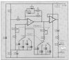
Apparently, if the output of OpAmp 1 was left unchecked, it's amplitude could become too large and clipping would occur, thereby destroying the shape of the sine waveform.
In order to prevent this, two diodes back to back and a resistor in series (D1,D2,R7) are used to somehow alter the gain of the Op-Amp and prevent this happening.

Of course, the components are in the negative feedback path for the Op-Amp so I understand why their presense could effect the overall gain of the amplifier, but how exactly does it operate? How does it sample the output amplitude and modify the gain of the Op-Amp accordingly?

Here's the circuit:

**broken link removed**
 

Attachments

  • WienOscillator.jpg
    WienOscillator.jpg
    33.1 KB · Views: 386
Once the output gets too large, the diodes will conduct - this effectively puts R7 and R6 in parallel, reducing the gain. With the reduced gain the output will then be too small to keep the diodes conducting, so they turn off again and the gain increases.

The overall gain will stabilise at a point just where the diodes are partially conducting.

It's a fairly crude way of stabilising a wien oscillator, and will give fairly high distortion - using a small filament lamp (of a suitable rating) is a low cost way of giving decent distortion figures.
 
Thanks for the advice.

I think this type of AGC may be suitable for my own application because the sinewave output isn't actually going to be used for audio purposes so some small distortion of the wave wont make too much difference, as long as the general shape is there.

I've worked out that when the diodes conduct the effective feedback resistance becomes 8.3 ohms, which because of the 6K7 input resistor, gives a gain of 1.22 rather than the original 3.9

As I understand it, a Wien oscillator requires a gain of 3 to sustain oscillation, so when the AGC kicks in this could temporarily effect the circuit's operation - is this the distortion you refer to?

If we're talking about using this kind of arrangement, then the output voltage will surely be restricted to around 1.4-2V? After that the diodes would be conducting all of the time...

Brian

Brian
 
BrianH said:
Thanks for the advice.

I think this type of AGC may be suitable for my own application because the sinewave output isn't actually going to be used for audio purposes so some small distortion of the wave wont make too much difference, as long as the general shape is there.

I've worked out that when the diodes conduct the effective feedback resistance becomes 8.3 ohms, which because of the 6K7 input resistor, gives a gain of 1.22 rather than the original 3.9

As I understand it, a Wien oscillator requires a gain of 3 to sustain oscillation, so when the AGC kicks in this could temporarily effect the circuit's operation - is this the distortion you refer to?

If we're talking about using this kind of arrangement, then the output voltage will surely be restricted to around 1.4-2V? After that the diodes would be conducting all of the time...

Wien oscillators commonly 'bounce' when you change frequency, your diode clipped one will have far less 'bounce' - mine using a small lamp takes a few seconds to stop bouncing, particularly at low frequencies.

Once your circuit stabilizes the distortion will be higher than other methods, but still reasonably low - if you're not planning using it for distortion measurements it doesn't matter - you certainly won't hear any distortion.

The actual output is (obviously) set by the gain in the opamp, the one I've being playing with recently includes a preset resistor in the feedback path, which you use to set the output level.
 
Status
Not open for further replies.

Latest threads

New Articles From Microcontroller Tips

Back
Top